23
6.3 Configuration of the PFU 2000
The DIP switch settings are shown in the “List of Control Parame-
ters”.
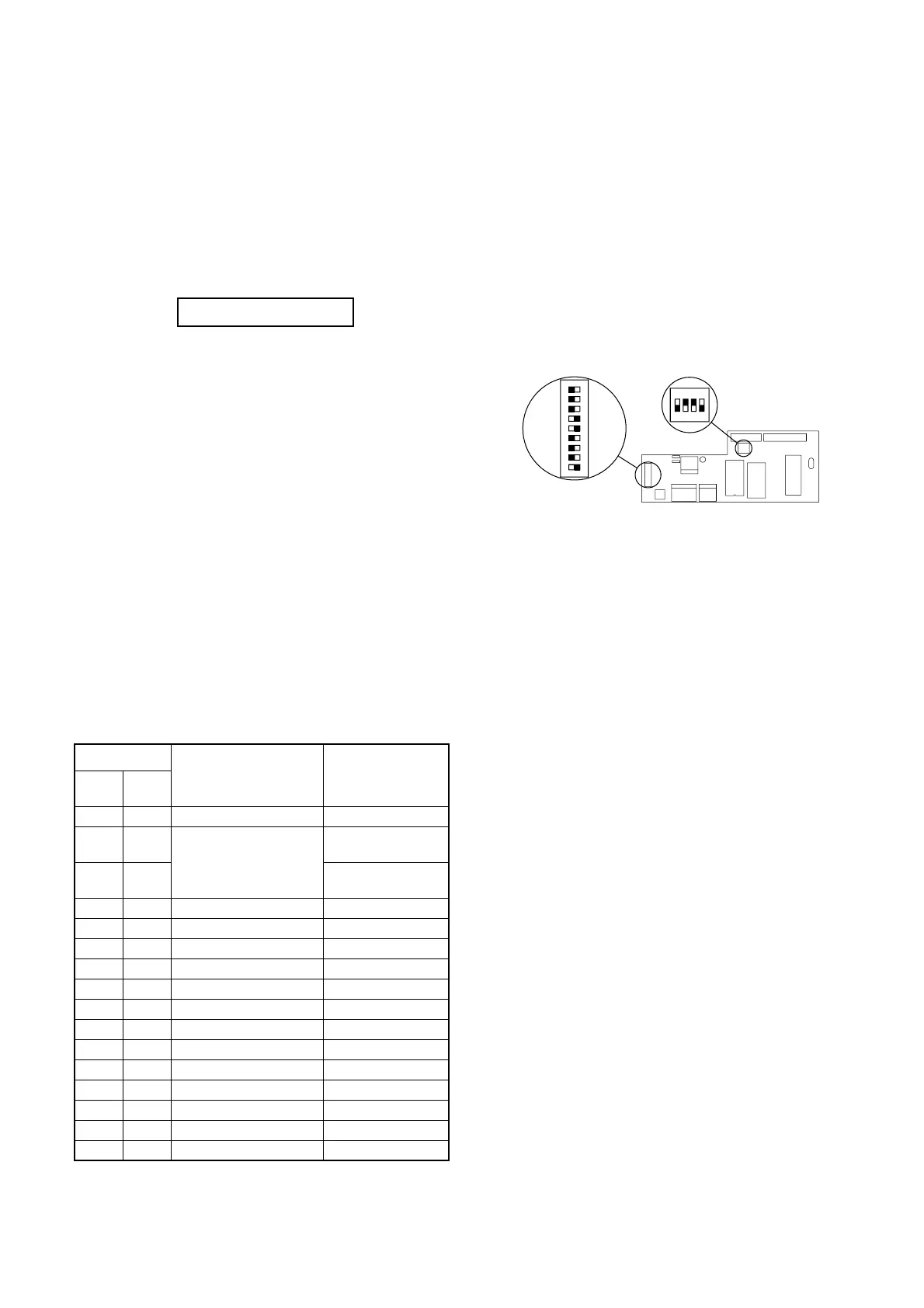
As an example, figure 31 shows the positions of DIPs 1 and 2 and
the following settings:
• Pump number of the first pump in the zone: 1.
• Water shortage monitoring with a contact signal.
• Operation on the basis of EPROM settings.
• No friction loss compensation.
• Discharge pressure transmitter: 4-20 mA signal.
• External setpoint: 0-10 V signal.
• Number of PFU 2000 units in the zone: 1.
• Number of pumps controlled: 2.
See also table in section 6.3.1 PFU 2000 DIP switch settings.
Fig. 31
ON
123456789
DIP 1
DIP 2
EPROM
ON
1234
TM00 5216 0296
6.1.1 Display rules
The displays appearing in the PMU 2000 menu are dependent on
the settings and the data transmitted from the units connected to
the GRUNDFOS BUS.
The displays which are not relevant according to the settings and
the units connected to the GRUNDFOS BUS will be suppressed.
All possible displays and values defined in the software will ap-
pear if they have not been suppressed as described above.
6.1.2 Status display
The status display is the first display that appears when the
PMU 2000 is switched on.
Fig. 30
If the PMU 2000 is not operated for 15 minutes, it will automati-
cally return to this display.
By pressing “Esc” repeatedly, you can always return to this dis-
play.
The status display indicates the following:
[I] Pumps 1, 2, 4 and 6 are operating.
[A] Fault indication on pump 3.
The fault can be identified in the fault indication menu.
[O] Pump 5 is not operating.
The reason can be found in the pump status menu.
[–] Pump 7 is allocated to a zone, but it has not yet been con-
nected to the PMU 2000 or the electricity supply to the pump
was never switched on.
[ ] Pump 8 has not been allocated to any zone.
A point between two pump numbers indicates that these pumps
have been connected to a PCU 2000. The display shows that
pumps 1, 2, 3 and 4 have been connected to a PCU 2000.
To find the units in the Control 2000 F, see the wiring diagram
and the mechanical layout.
6.2 Frequency converter settings
The frequency converter is delivered with the following settings:
The settings which are not shown in the table are all default set-
tings.
202 and 205 must be set to the same value.
The VLT 2800 will display the menu numbers, but no text.
Menu
Function Setting
VLT
2800
VLT
6000
001 001 LANGUAGE ENGLISH
101
VT CHARACT.
Variable torque
medium
101
MULTIPLE
MOTORS
102 102 MOTOR POWER Acc. to motor data
103 103 MOTOR VOLTAGE Acc. to motor data
104 104 MOTOR FREQUENCY Acc. to motor data
105 105 MOTOR CURRENT Acc. to motor data
106 106 MOTOR NOM. SPEED Acc. to motor data
201 201 MIN. FREQUENCY 0 Hz
202 202 MAX. FREQUENCY 51 Hz - 53 Hz
204 204 MIN. REFERENCE 0 Hz
205 205 MAX. REFERENCE 51 Hz - 53 Hz
207 206 RAMP UP TIME 1-3 secs.
208 207 RAMP DOWN TIME 1-3 secs.
323 323 RELAY 1 FUNCTION READY
405 400 RESET FUNCTION AUTOMATIC x 10
100 1.2.3.4 5 6 7 8
Status I I A I O I -

 Loading...


