9
3.1.4 Cascade control
Cascade control ensures automatic matching of the performance
to the system demand by cutting in/out the required number of
pumps.
The controller will operate the system with as few pumps as pos-
sible.
The frequency of starts and stops is limited by the setting of mini-
mum and medium switching sequences.
For further information, see sections
3.2.9 Minimum switching sequence,
3.2.10 Medium switching sequence and
3.2.17 Minimum pump speed limit.
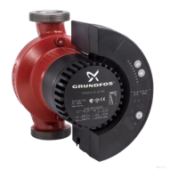
3.1.5 Manual on/off and setting to max. or local
Operation with PFU 2000 RAM / PMU 2000 settings:
Fig. 10
In the start/stop menu, the “On/Off” button on the PMU 2000
gives quick access to:
• manual on/off of zone and setting to max. or local,
• manual on/off of individual pumps.
In this menu, the zone and the pumps allocated to this zone ap-
pear one by one when the arrow buttons are pressed.
The operating condition of the zone or pump in question is dis-
played in the top line. In the bottom line, a new status can be se-
lected.
Start/stop of zones (display 300):
•“on”
All pumps in the zone are ready for operation.
•“off”
All pumps in the zone are switched off.
•“max.”
All pumps in the zone are operating at maximum performance.
• “local”
The controller has been set to local mode and will operate ac-
cording to the local control parameter settings.
See section 6.3.1 PFU 2000 DIP switch settings.
If the function selector in the PFU 2000 has been turned to posi-
tion MAX, the setpoint influences, “clock program” and “remote
on/off” are not effective.
Start/stop of pumps (display 301):
•“on”
The pump is ready for operation.
•“off”
The pump is switched off.
Operation with PFU 2000 EPROM settings:
The controller will operate according to the local control parame-
ter settings.
For further information, see section
6.3.1 PFU 2000 DIP switch settings.
On
Off
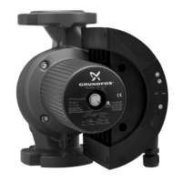
3.1.3 Closed-loop control
The closed-loop controller (a control system with a feed-back sig-
nal from a transmitter) is programmed for operation of centrifugal
pumps and takes their influence on the hydraulic system into ac-
count.
Fig. 8
The only control parameter to be set to adapt the controller to the
system conditions is “system time” (display 204), instead of PID
parameters as is the case with conventional closed-loop control-
lers.
• Operation with PFU 2000 RAM / PMU 2000 settings:
With the settings in the start/stop menu (displays 300 and 301)
and with the function selector in the PFU 2000 within the range
from 0% to 100%, the closed-loop controller is operating.
• Operation with PFU 2000 EPROM settings:
With the function selector in the PFU 2000 within the range
from 0% to 100%, the closed-loop controller is operating.
Fig. 9
For further information, see section
3.2.5 Setpoint influences.
PMU 2000
PFU 2000
PP
GRUNDFOS BUS
TM00 8277 2596
100%0%
MAXSTOP
Setpoint
Function selector in the PFU 2000
TM00 5217 2796

 Loading...