17
7.11 Wiring diagrams for expansion modules
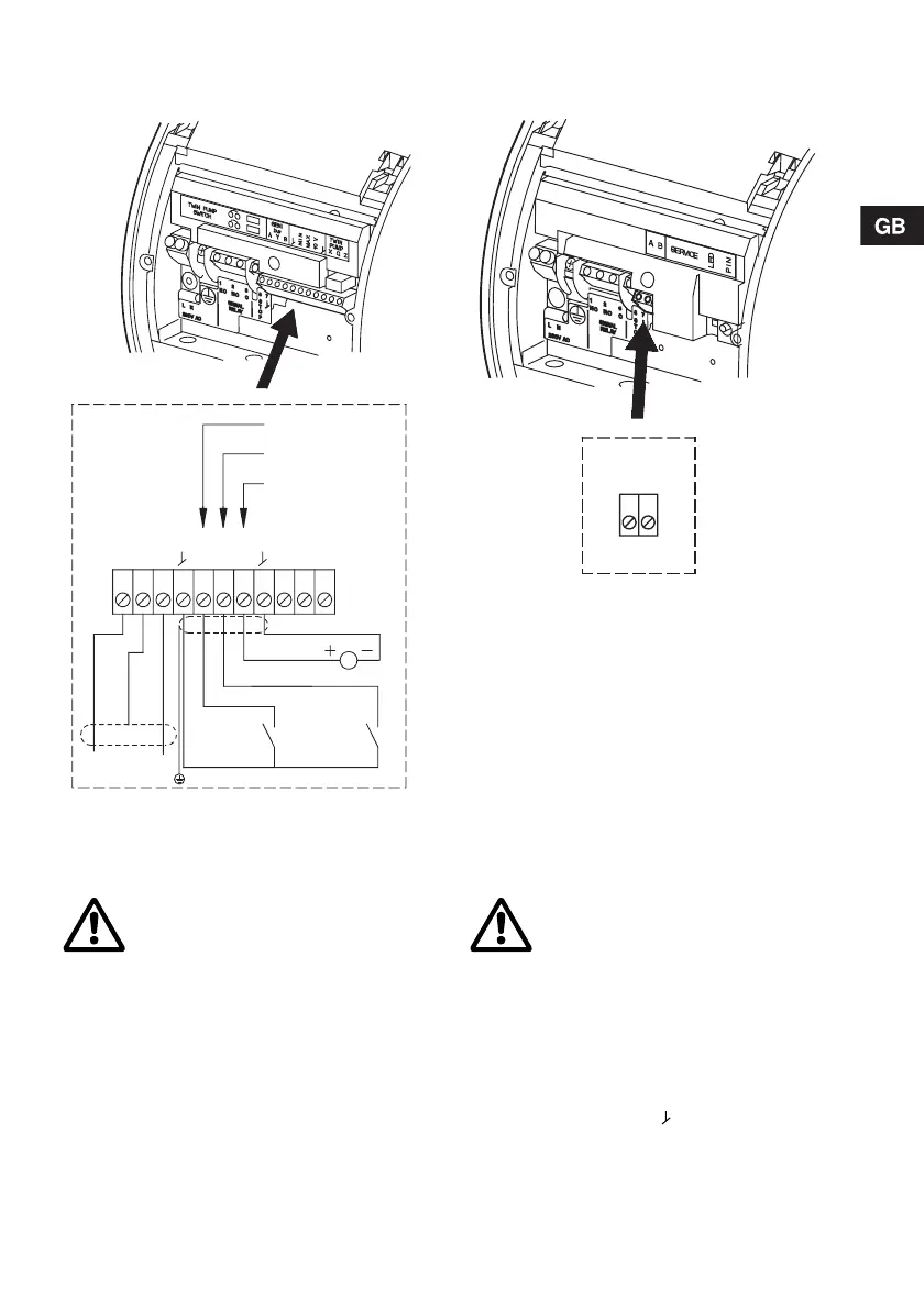
Fig. 15 GENI module Fig. 16 LON module
Note:
• If the 0-10 V input is used, there must be a connection across terminals MIN and (input for min. curve
must be closed).
• All cables used must be heat-resistant up to +85 °C.
• All cables used must be installed in accordance with EN 60204-1 and EN 50174-2: 2000.
Concerning demands on signal wires and signal transmitters, see section 11. Technical data.
Connection examples (GENI module) can be found on pages 338 to 341.
TM02 0236 1007
TM02 0237 0904
Warning
• Wires connected to
– supply terminals,
– outputs NC, NO, C and
– start/stop inputs, A, Y, B, MIN,
MAX, 10 V
must be separated from each other
and from the supply by reinforced
insulation.
• All wires connected to a terminal
block must be tied up at the
terminals.
Warning
• Twisted-pair cable.
• Wires connected to
– supply terminals,
– outputs NC, NO, C and
– start/stop inputs, A, B
must be separated from each other
and from the supply by reinforced
insulation.
• All wires connected to a terminal
block must be tied up at the
terminals.
4
XQZBYA
MIN
MAX
10 V
5 6 7 9 10 11 12 21 22 23
DC 0-10 V
Min.
Screen
Max.
Bus signal
Min. curve
Max. curve
Analog 0-10 V input
Twin-head
pump
BA
Bus signal

 Loading...