19
8. Setting the pump
For the setting of the pump, use:
• control panel
• R100 remote control
• bus communication (not described in detail in
these instructions, contact Grundfos).
The table shows the application of the individual
operating units and in which section the function has
been described.
"–" = not available with this operating unit.
8.1 Factory setting
The pump is factory-set to AUTOADAPT without
automatic night-time duty.
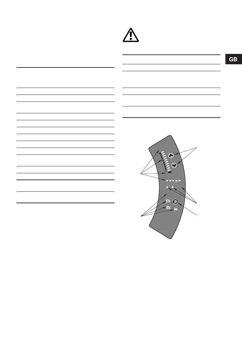
8.2 Control panel
The control panel, fig. 19, incorporates:
For further information, see section 9. Fault finding
chart.
Fig. 19 Control panel
Possible settings
Control
panel
R100
AUTOADAPT 8.2.1 8.7.1
Automatic night-time duty 8.2.1 8.7.2
Proportional-pressure
control
8.2.1 8.7.1
Constant-pressure control 8.2.1 8.7.1
Setpoint setting 8.2.2 8.5.1
Max. curve duty 8.2.3 8.5.2
Min. curve duty 8.2.4 8.5.2
Constant-curve duty – 8.5.2
Temperature influence – 8.7.3
Activation/deactivation of
pump buttons
– 8.7.4
Allocation of pump number – 8.7.6
Start/stop 8.2.5 8.5.2
Resetting of fault
indications
8.2.6 8.5.3
Reading of various data –
8.6.1 -
8.6.7
Warning
At high liquid temperatures, the pump
may be so hot that only the buttons
should be touched to avoid burns.
Pos. Description
1 Buttons for setting
2
• Indicator lights for operating and fault
indication and
• symbol for indication of external control
3 Button for change of control mode
4
Light symbols for indication of control
mode and night-time duty
5
Light fields for indication of head, flow and
operating mode
TM03 8798 2507
EXT
Q
100%
MAX
STO P
5
4
1
2
3
AUTO
ADAPT
H

 Loading...