7
4. Installation
Arrows on the pump housing indicate the liquid flow
direction through the pump.
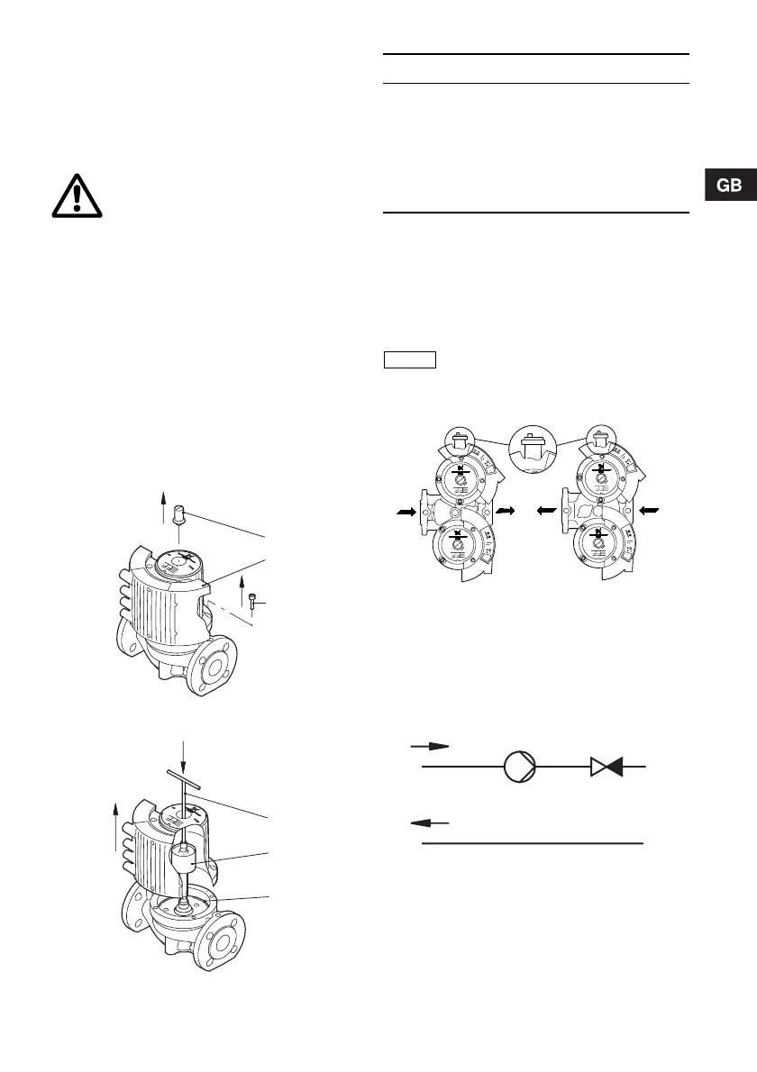
4.1 Changing the control box position
Change the control box position as follows:
1. Remove the inspection screw (1) and the four
screws (2) in the stator housing, see fig. 1.
2. Lift off the stator housing (3). Keep the rotor (4) in
place using a suitable tool, e.g. a T-key (M8) (5),
see fig. 2.
3. Check that the O-ring (6) is intact.
A defective O-ring must be replaced.
4. Hold the stator housing/control box (3) in the
desired position.
5. Lower the stator housing over the rotor.
Keep the rotor in place as described in point 2.
6. Fit and tighten the four screws and the inspection
screw.
Fig. 1 Removing the control box
Fig. 2 Changing the control box position
4.2 Twin-head pumps
Twin-head pumps are supplied fitted with a GENI
module on each control box. The modules are
connected via a cable. The modules determine the
operating mode of the pump, see section
7.12.1 Control of twin-head pumps.
The automatic air vent is not supplied with the pump.
Fig. 3 Automatic air vent
4.3 Non-return valve
If a non-return valve is fitted in the pipe system, see
fig. 4, it must be ensured that the set minimum
discharge pressure of the pump is always higher
than the closing pressure of the valve. This is
especially important in proportional-pressure control
mode (reduced head at low flows).
Fig. 4 Non-return valve
Warning
Before any dismantling of the pump,
the system must be drained or the
isolating valves on either side of the
pump must be closed as the pumped
liquid may be scalding hot and under
high pressure.
TM02 5506 3402TM02 5507 3402
2
3
1
5
4
6
Pos. Description
1 Inspection screw
2Screw
3 Stator housing/control box
4 Rotor
5T-key
6 O-ring
Caution
Twin-head pumps mounted in
horizontal pipes must be fitted with an
automatic air vent (Rp 1/4) in the upper
part of the pump housing, see fig. 3.
TM03 8831 2607TM02 0640 0301

 Loading...