English (GB)
11
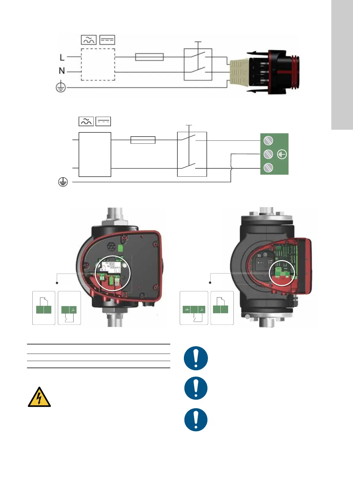
3.5.2 Wiring diagrams
Fig. 16 Example of a plug-connected motor with a main switch, backup fuse and additional protection
Fig. 17 Example of a mains-connected motor with a main switch, backup fuse and additional protection
Fig. 18 Connection to external control
TM05 5277 3016
External switch
Fuse
RCD/RCCB
TM06 8503 0817
TM06 9106 4517 - TM06 8060 0717
External switch
Fuse
RCD/RCCB
Pos. Description
1 Plug-connected versions
2 Terminal-connected versions
WARNING
Electric shock
Minor or moderate personal injury
- Separate wires connected to supply terminals,
outputs NC, C and start-stop input from each other
and from the supply by means of reinforced
insulation.
Make sure that the fuse is dimensioned according to
the nameplate and local regulations.
Connect all cables in accordance with local
regulations.
Make sure that all cables are heat-resistant up to 75
°C.
Install all cables in accordance with EN 60204-1 and
EN 50174-2:2000.
 Loading...