English (GB)
9
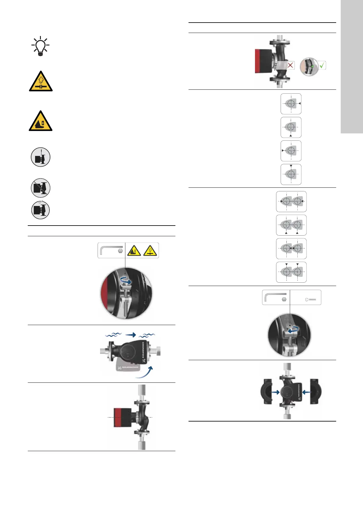
3.4.4 Changing the control box position
The warning symbol on the clamp holding the pump
head and pump housing together indicates that there
is a risk of personal injury. See specific warnings
below.
CAUTION
Pressurised system
Minor or moderate personal injury
- Pay special attention to any escaping vapour
when loosening the clamp.
CAUTION
Crushing of feet
Minor or moderate personal injury
- Do not drop the pump head when loosening the
clamp.
Fit and tighten the screw holding the clamp to 8 Nm ±
1 Nm. Do not apply more torque than specified even
though water is dripping from the clamp. The
condensed water is most likely coming from the drain
hole under the clamp.
Check the position of the clamp before you tighten
the clamp. Incorrect position of the clamp will cause
leakage from the pump and damage the hydraulic
parts in the pump head.
Step Action Illustration
1
Loosen the screw
in the clamp that
holds the pump
head and pump
housing together. If
you loosen the
screw too much,
the pump head will
be completely
disconnected from
the pump housing.
TM05 2867 3016
2
Carefully, turn the
pump head to the
desired position.
If the pump head is
stuck, loosen it with
a light blow of a
rubber mallet.
TM05 5526 3016
3
Place the control
box in horizontal
position so that the
Grundfos logo is in
vertical position.
The motor shaft
must be in
horizontal position.
TM05 5527 3016
4
Due to the drain
hole in the stator
housing, position
the gap of the
clamp as shown in
step 4a or 4b.
TM05 2870 3016
4a
Single-head
pump:
Position the clamp
so that the gap
points towards the
arrow.
It can be in position
3, 6, 9 or 12
o'clock.
TM05 2918 3016
4b
Twin-head pump:
Position the clamps
so that the gaps
point towards the
arrows.
They can be in
position 3, 6, 9 or
12 o'clock.
TM05 2917 3016
5
Fit and tighten the
screw holding the
clamp to 8 ± 1 Nm.
Do not retighten
the screw if
condensed water is
dripping from the
clamp.
TM05 2872 3016
6
Fit the insulating
shells.
Insulating shells for
pumps in
air-conditioning
and cooling
systems must be
ordered separately.
TM05 5529 3016
Step Action Illustration
 Loading...