English (GB)
12
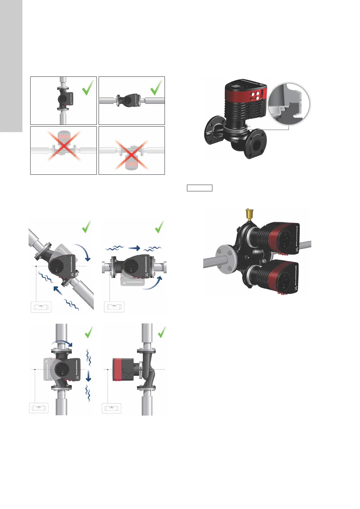
3.3 Positioning
Always install the pump with horizontal motor shaft.
• Pump installed correctly in a vertical pipe. See fig. 10, pos. A.
• Pump installed correctly in a horizontal pipe. See fig. 10,
pos. B.
• Do not install the pump with vertical motor shaft. See fig. 10,
pos. C and D.
Fig. 10 Pump installed with horizontal motor shaft
3.4 Control box positions
To ensure adequate cooling, the control box must be in horizontal
position with the Grundfos logo in vertical position. See fig. 11.
Fig. 11 Pump with control box in horizontal position
If the pump head is removed before the pump is installed in the
pipework, pay special attention when fitting the pump head to the
pump housing:
1. Gently lower the pump head with rotor shaft and impeller into
the pump housing.
2. Make sure that the contact face of the pump housing and that
of the pump head are in contact before the clamp is tighened.
See fig. 12.
Fig. 12 Fitting the pump head to the pump housing
Fig. 13 Automatic air vent
TM05 5518 3812
TM05 5519 3812
TM05 5520 3812
TM05 5521 3812
TM05 5522 3812
TM05 5837 4112
Twin-head pumps installed in horizontal pipes
must be fitted with an automatic air vent (Rp 1/4)
in the upper part of the pump housing.
See fig. 13.
TM05 6062 4412

 Loading...