English (GB)
18
6. Settings
7. Control panel
7.1 Elements on the control panel
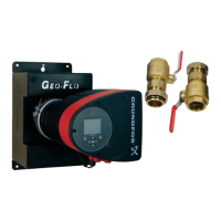
Fig. 17 Control panel
The control panel on the pump comprises the following:
7.2 Grundfos Eye
The Grundfos Eye is on when the power supply has been
switched on. See fig. 17, pos. 1.
The Grundfos Eye is an indicator light providing information about
the actual pump status.
The indicator light will flash in different sequences and provide
information about the following:
• power on/off
• pump alarms.
The function of the Grundfos Eye is described in section
10.1 Grundfos Eye operating status.
If a fault is indicated, correct the fault and reset the pump by
switching the power supply off and on.
7.3 Light fields indicating the pump setting
The pump has nine optional performance settings which can be
selected with the push-button. See fig. 17, pos. 3.
The pump setting is indicated by eight light fields in the display.
See fig. 17, pos. 2.
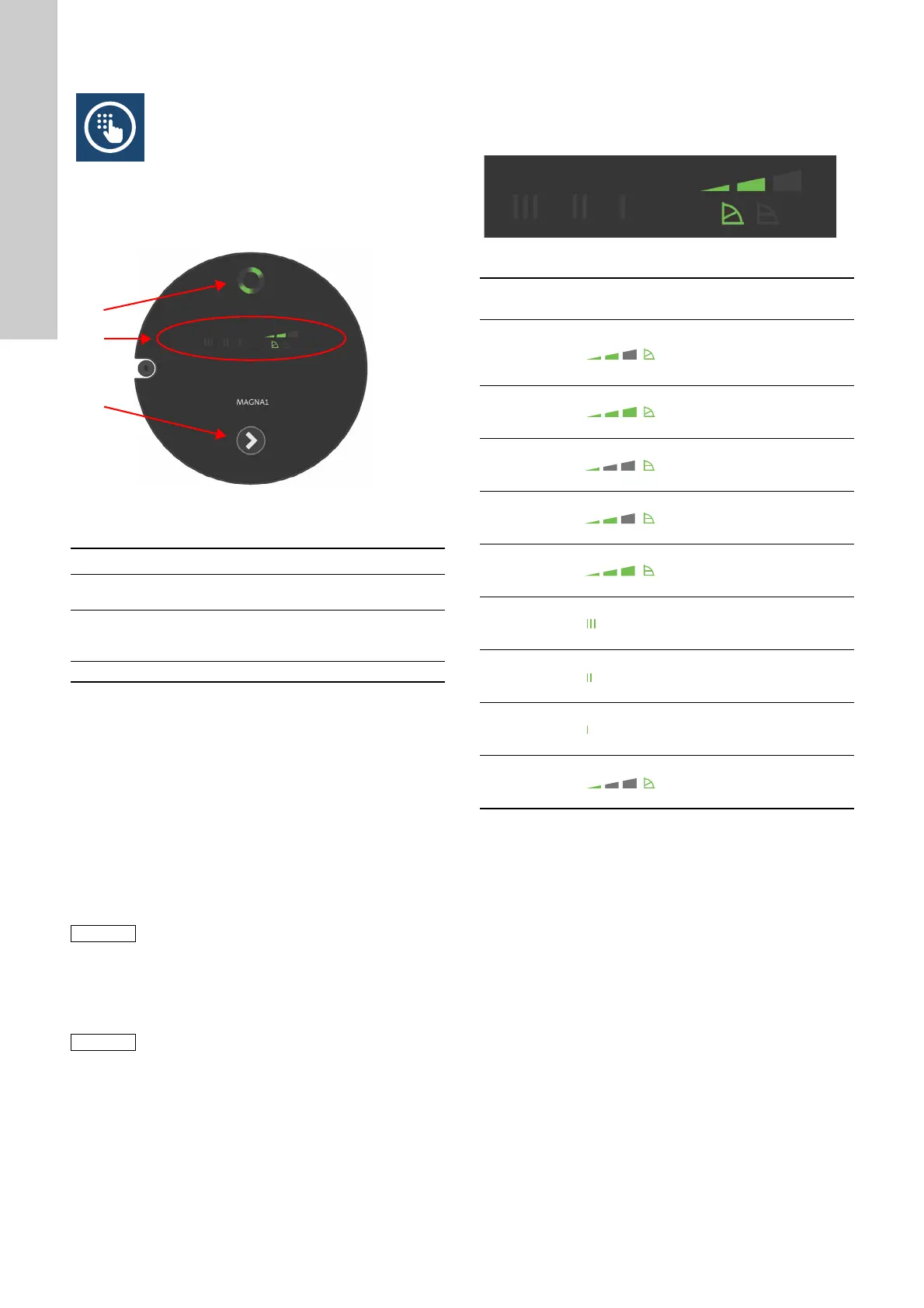
Fig. 18 Factory setting, PP2
TM05 5552 3812
Pos. Description
1
Grundfos Eye operating status.
See section 7.2 Grundfos Eye.
2
Eight light fields indicating the pump setting.
See section 7.3 Light fields indicating the pump
setting.
3 Push-button for selection of pump setting.
Faults preventing the pump from operating
properly (for example blocked rotor) are
indicated by the Grundfos Eye. See section
10.1 Grundfos Eye operating status.
If the pump impeller is rotated, for example when
filling the pump with water, sufficient energy can
be generated to light up the control panel even if
the power supply has been switched off.
TM05 5553 3812
Button
presses
Active light fields Description
0
Intermediate
proportional-pressure
curve, referred to as PP2
1
Highest
proportional-pressure
curve, referred to as PP3
2
Lowest
constant-pressure curve,
referred to as CP1
3
Intermediate
constant-pressure curve,
referred to as CP2
4
Highest
constant-pressure curve,
referred to as CP3
5
Constant curve/constant
speed III
6
Constant curve/constant
speed II
7
Constant curve/constant
speed I
8
Lowest
proportional-pressure
curve, referred to as PP1
 Loading...