English (GB)
9
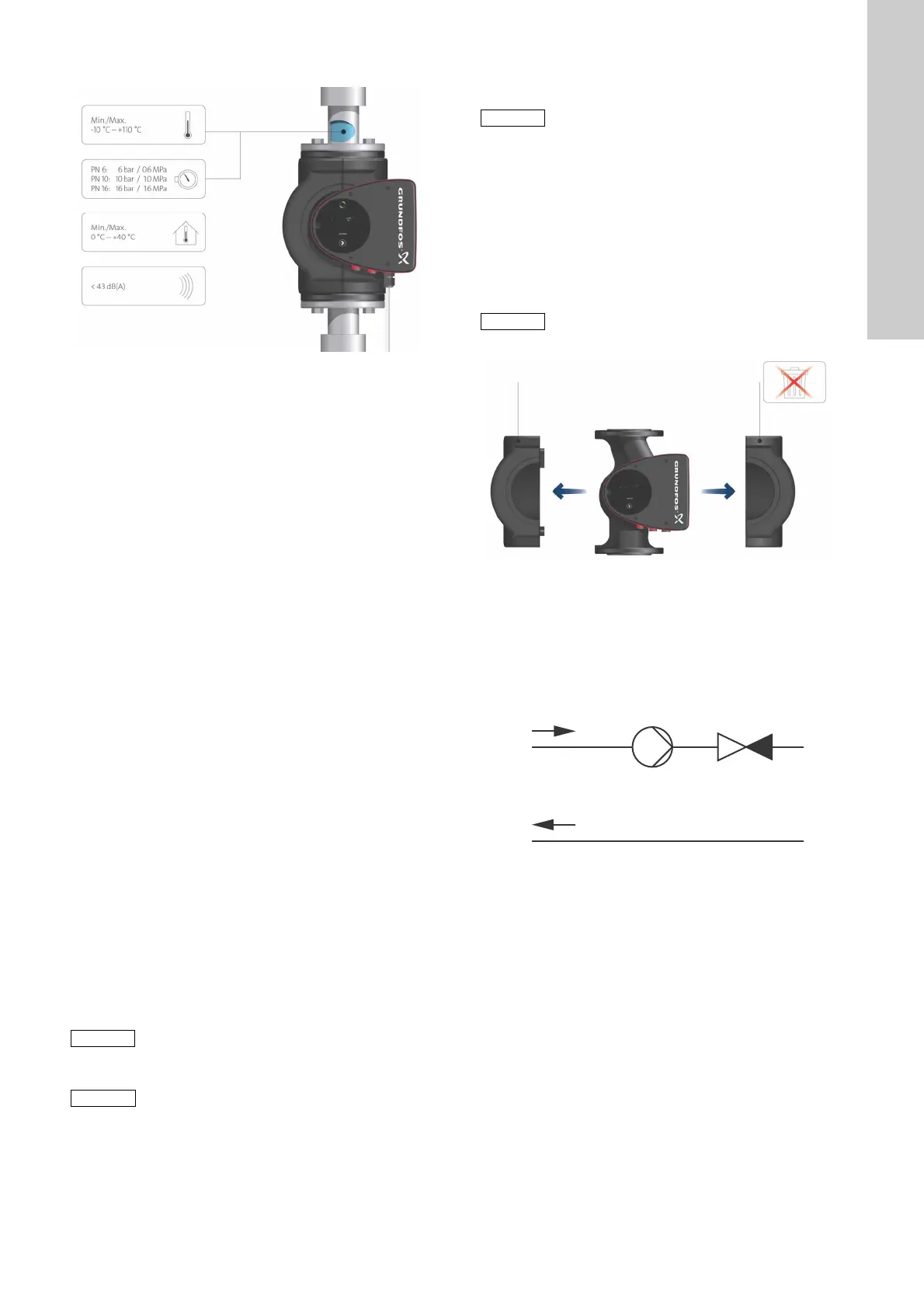
2.3 Operating conditions
Fig. 3 Operating conditions
2.3.1 Liquid temperature
See fig. 3, pos. 1.
Continuously: -10 to +110 °C.
2.3.2 System pressure
See fig. 3, pos. 2.
The maximum permissible system pressure is stated on the pump
nameplate. See fig. 6.
2.3.3 Test pressure
The pumps can withstand test pressures as indicated in
EN 60335-2-51. See below.
• PN 6: 7.2 bar
• PN 10: 12 bar
• PN 6/10: 12 bar
• PN 16: 19.2 bar.
During normal operation, the pump should not be used at higher
pressures than those stated on the nameplate. See fig. 6.
Pumps tested with water containing anti-corrosive additives are
taped on the suction and discharge ports to prevent residual test
water from leaking into the packaging. Remove the tape before
installing the pump.
The pressure test has been made with water containing
anti-corrosive additives at a temperature of +20 °C.
2.3.4 Ambient temperature
See fig. 3, pos. 3.
0 to +40 °C.
The control box is air-cooled. Therefore, it is important that the
maximum permissible ambient temperature is not exceeded
during operation.
During transport: -30 to +55 °C.
2.3.5 Sound pressure level
See fig. 3, pos. 4.
The sound pressure level of the pump is lower than 43 dB(A).
2.4 Frost protection
2.5 Insulating shells
Insulating shells are available for single-head pumps only.
The heat loss from the pump and pipework can be reduced by
insulating the pump housing and the pipework. See fig. 4.
• Insulating shells for pumps in heating systems are supplied
with the pump.
• Insulating shells for pumps in air-conditioning and cooling
systems (down to -10 °C) are available as accessories and
must be ordered separately. See section 11.1 Insulating kits
for air-conditioning and cooling systems.
The fitting of insulating shells will increase the pump dimensions.
Fig. 4 Insulating shells
2.6 Non-return valve
If a non-return valve is fitted in the pipe system (fig. 5), ensure
that the set minimum discharge pressure of the pump is always
higher than the closing pressure of the valve. This is especially
important in proportional-pressure control mode (reduced head at
low flow). The first non-return valve is included in the pump
setting as the minimum setpoint is 1.0 metre.
Fig. 5 Non-return valve
TM05 5511 3812
If the pump is not used during periods of frost,
necessary steps must be taken to prevent frost
bursts.
Additives with a density and/or kinematic
viscosity higher than those/that of water will
reduce the hydraulic performance.
Limit the heat loss from the pump housing and
pipework.
Pumps for heating systems are factory-fitted with
insulating shells. Remove the insulating shells
before installing the pump.
TM05 5512 3812TM05 3055 0912

 Loading...