English (GB)
9
Filling with oil
1. Turn the pump so that the oil filling holes are placed opposite
each other, pointing upwards.
Fig. 1 Oil filling holes
2. Pour oil into the oil chamber.
3. Fit the oil screws with new gaskets.
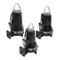
8.5 Cleaning and inspecting the pump
Clean the pump on site at regular intervals by following this
procedure:
• Lift the pump out of the pit.
• Hose down the pump externally, using a high-pressure cleaner
at maximum 100 bar.
• Remove caked dirt from the motor to ensure good heat
conductivity. Use a mild detergent approved for disposal into
the sewage system.
• If necessary, scrub the pump, using a soft brush.
Visual inspection of the pump must include the following points:
• Search for cracks or other external damage.
• Check the lifting bracket and lifting chain for wear and
corrosion.
• Inspect the power cable for cracks or lacerations in the
sheath, for kinks or for other damage.
• Inspect visible parts of the cable entry for cracks.
• Check that the cable is firmly connected to the top cover.
• Check all visible screws for self-loosening and tighten, if
necessary.
The pump is fitted with a vent valve at the bottom of the cooling
jacket. Remove and clean the valve, if necessary. Clean the vent
hole before refitting the valve after cleaning.
8.6 Checking the sensors
Make the measurements from the free end of the cable (10 m),
the other end of the cable is connected to the pump. In case the
pump cable is longer than 10 m, contact Grundfos for correct
values.
A Grundfos sensor test box can be used for check measuring the
sensors. The sensor test box gives the response values by
means of LEDs, to indicate if the sensor is ok. See section
8.6.1 Checking by means of a test box.
It is also possible to measure the sensors by means of a standard
instrument measuring Amperes and Ohms. See section
8.6.2 Checking by means of a standard instrument.
8.6.1 Checking by means of a test box
Fig. 2 Te xt box
Proceed as follows:
1. Connect the text box and sensors according the wiring
diagram. See fig 3.
Fig. 3 Wiring diagram for test box and sensors
2. Observe led lights on the test box and compare to the table
below.
TM06 6005 0216
Sensor check measurements must be made by
Grundfos or persons authorised by Grundfos.
TM04 8000 2610TM04 8022 2410
Fault LED Output [mA]
None Green 4-20
Moisture Red 0
No pump Red 0
Temperature Red 4-20
WIO Green 0
WIO - air (WIA) Green 3.5
WIO - water Green 22
T
M
T1/P1 T1
T2/P2
T2
T5/P5
T5
mA
 Loading...