English (GB)
11
9.2 Replacing the pin housing
9.2.1 Removing the pin housing
1. See section 9.1.1 Removing the cable.
2. See section 9.4.7 Removing the motor top.
3. Remove the earthing screw (173) including the washer
(173a).
4. Disconnect the wire pins from the pin housing (176).
5. Remove the plug protector (177), including the pin housing
(176).
6. Remove the pin housing (176) by pressing it up with the pin
pusher (D) below the pin housing.
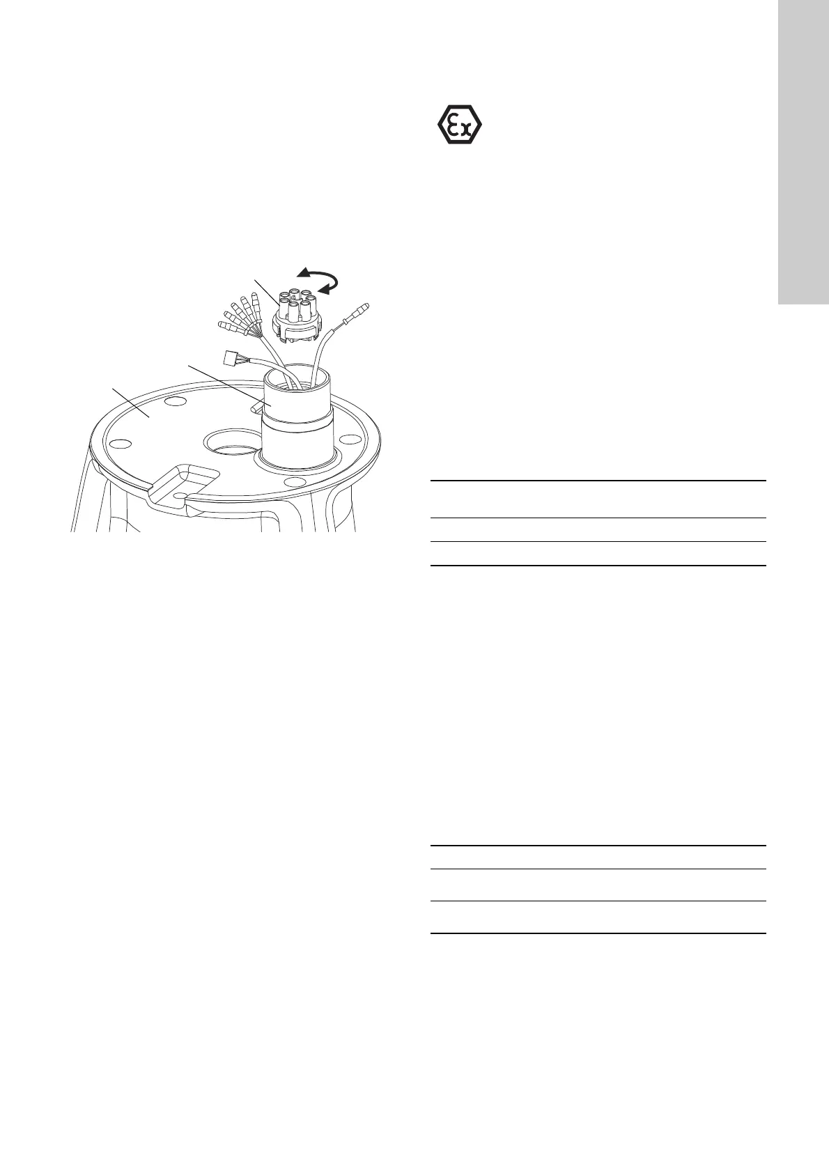
9.2.2 Fitting the pin housing
Fig. 7 Fitting the pin housing
1. Pull the wires (coming from the stator) gently through the plug
protector (177).
2. Fit the plug housing (177) to the stator housing (55).
3. Connect the wires (coming from the stator) to the pin housing
(176). See section 12.5.2 Wiring diagrams.
4. Fit the new pin housing (176) in the plug protector (177).
5. Connect the earthing screw (173) and washer (173a).
6. Assemble the pump according to the instructions in section
9.5 Assembling.
9.3 Replacing the protection sensors
For sensor positions, see section 12.4 Sensor positions.
All SE1 and SEV pumps have thermal protection incorporated in
the stator windings.
Pumps without sensor
Pumps without sensor have a thermal switch. Via the pump
controller safety circuit, the thermal switch will stop the pump by
breaking the circuit in case of high overtemperature
(approximately 150 °C). The thermal switch will reclose the circuit
after cooling.
The maximum operating current of the thermal switch is 0.5 A at
500 VAC and cos φ 0.6. The switch must be able to break a coil in
the supply circuit.
In the case of standard pumps, when closing the circuit after
cooling, the thermal switch can (restart the pump automatically
via the controller.
Pumps with sensor
Pumps with sensor have either a thermal switch and a Pt1000
sensor or a thermistor (PTC) in the windings, depending on the
installation site.
To find out whether the pump is fitted with a thermal switch or a
PTC thermistor, measure the motor winding resistance. See the
table below.
Via the pump controller safety circuit, the thermal switch or the
thermistor stops the pump by breaking the circuit in case of high
temperature, approximately 150 °C. The thermal switch or the
thermistor recloses the circuit after cooling.
The maximum operating current for both the Pt1000 and the
thermistor is 1 mA at 24 VDC.
Moisture switch and WIO sensor
The moisture switch is an NC switch (normally closed). In case of
moisture, the circuit is broken, and the current supply to the pump
is interrupted. If the moisture switch has been activated, it must
be replaced.
The WIO sensor measures the water content in the oil and
converts the value into an analog current signal. The two sensor
conductors are for power supply as well as for carrying the signal
to the IO 113 module. The sensor measures the water content
from 0 to 20 %. It also sends a signal if the water content is
outside the normal range (warning), or if there is air in the oil
chamber (alarm).
TM06 9234 2017
The protection sensors must be replaced by
Grundfos or an Ex-approved service centre.
Without
cable
With 10 m
cable
With 15 m
cable
Thermal switch < 50 mΩ < 320 mΩ < 390 mΩ
PTC thermistor > 100 mΩ > 370 mΩ > 440 mΩ
Fault indication Reaction
Water in oil
Warning.
The pump keeps running.
Sensor not covered by oil
Alarm.
The pump stops.
 Loading...