English (GB)
15
9.4.5 Removing the rotor
1. See section 9.4.4 Removing the shaft seal.
2. Remove the screws (182).
3. Remove the lower bearing cover (59).
4. Fit two screws (182) in the upper bearing cover (60), and
tighten them until the rotor (172) is free.
5. Carefully pull out the rotor.
6. Remove the corrugated spring (158) from the stator housing
(55).
7. In case of a WIO sensor, remove the sensor (521) from the
bracket (522). Place the sensor inside the stator (48).
8. Remove the O-rings (109 and 108).
9.4.6 Removing the bearings
1. See section 9.4.5 Removing the rotor.
2. Pull out the lower bearing retainer (60) including the lower
bearing (153).
3. Remove the O-ring (102).
4. Gently tap the inner ring of the lower bearing (153) to remove
it from the lower bearing cover (60).
5. Remove the O-ring (108).
6. Remove the upper bearing (154), using a bearing puller.
9.4.7 Removing the motor top
1. See section 9.4.4 Removing the shaft seal.
2. Remove the cable plug. See section 9.1 Checking and
replacing the cable.
3. Place the motor housing in vertical position on wooden bars.
4. Remove the screw (183) and washer (183a).
5. Remove the motor top (151) by lifting the pump slowly by the
lifting bracket (190) using a crane.
6. Remove the O-ring (37b).
9.4.8 Removing the sleeve
1. See section 9.4.7 Removing the motor top.
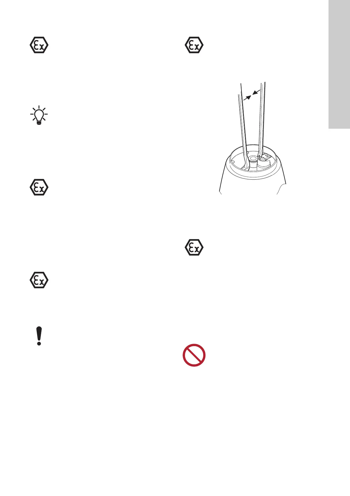
2. Pull the sleeve (150) free of the stator housing (55), using two
crowbars. See fig. 15.
Fig. 15 Removing the sleeve
3. Remove the O-rings (37a).
4. Remove the O-ring (159).
9.4.9 Removing the stator housing
1. See section 9.4.8 Removing the sleeve.
2. Remove the screws (184) and washers (184a).
3. Fit the motor top (151) with screw (183).
4. Turn the pump in horizontal position and support with wooden
blocks or similar support.
5. Fit one of the screws (184) into the screw hole to loosen the
intermediate flange (155).
6. In case of sensor version: Pull the WIO sensor out of the
stator housing.
7. Carefully pull the intermediate flange (55) free and, at the
same time, push the wire of the WIO sensor (521) through the
flange.
8. Remove the WIO sensor and moisture switch. See section
9.3 Replacing the protection sensors.
This work must be carried out by Grundfos or an Ex-
approved service centre.
The upper bearing (154) is removed together with the
rotor.
This work must be carried out by Grundfos or an Ex-
approved service centre.
This work must be carried out by Grundfos or an Ex-
approved service centre.
Be careful not to damage the plug housing (177).
This work must be carried out by Grundfos or an Ex-
approved service centre.
TM03 1673 2605
This work must be carried out by Grundfos or an Ex-
approved service centre.
Do not use force when pulling the sensor wire.
Do not pinch the sensor under the intermediate
flange.
 Loading...