7
English (US)
8. Mechanical installation
Install the pump in a dry well-ventilated, but frost-free position.
When installing pumps with oval bolt holes in the pump flange,
use washers as shown in fig. 4.
Fig. 4 Use of washers for oval bolt holes
Arrows on the pump housing show the direction of flow of liquid
through the pump.
You can install the pump in horizontal or vertical pipes.
For inspection and removal of motor or pump head, a clearance
of 11.81" (300 mm) is required above the motor. See fig. 5.
Fig. 5 Required clearance above the motor
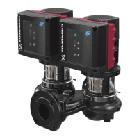
Twin-head pumps installed in horizontal pipes must be fitted with
an automatic air vent in the upper part of the pump housing.
See fig. 6.
The automatic air vent is not supplied with the pump.
Fig. 6 Automatic air vent
If the liquid temperature falls below the ambient temperature,
condensation may form in the motor during inactivity. In this case,
make sure that one of the drain holes in the motor flange is open
and points downwards. See fig. 7.
Fig. 7 Drain hole in motor flange
If twin-head pumps are used for pumping liquids with a
temperature below 32 °F (0 °C), condensed water may freeze
and cause the coupling to get stuck. You can solve the problem
by installing heating elements. Whenever possible, install the
pump with the motor shaft in horizontal position. See fig. 6.
8.1 Pipework
Fit isolating valves on either side of the pump to avoid draining
the system if the pump needs to be cleaned or repaired.
The pump is suitable for pipeline mounting, provided that the
pipes are adequately supported on either side of the pump.
Single-head pumps are designed for pipeline mounting only.
Twin-head pumps are prepared for installation on a mounting
bracket or base plate.
When installing the pipes, make sure that the pump housing is
not stressed by the pipework.
The suction and discharge pipes must be of an adequate size,
taking the pump inlet pressure into account.
To avoid sediment build-up, do not fit the pump at the lowest point
of the system.
Install the pipes so that air locks are avoided, especially on the
suction side of the pump. See fig. 8.
Fig. 8 Correct pipework on the suction side of the pump
If there is any risk of the pump running against a closed discharge
valve, ensure a minimum liquid flow through the pump by
connecting a bypass/a drain to the discharge pipe. You can for
instance connect the drain to a tank. A minimum flow rate equal
to 10 % of the flow rate at maximum efficiency is needed at all
times.
Flow rate and head at maximum efficiency are stated on the
pump nameplate.
Warning
When pumping hot or cold liquids, make sure
that persons cannot accidentally come into
contact with hot or cold surfaces.
In order to maintain the UL mark, additional
installation procedures must be followed.
See page 50.
TM01 0683 1997
The motor must never fall below the horizontal
plane.
TM05 7916 1613TM05 7983 1713
TM05 7917 1613
Observe the conditions in section 11. User
interfaces.
TM00 2263 0195
The pump must not run against a closed
discharge valve as this will cause an increase in
temperature/formation of steam in the pump
which may cause damage to the pump.
 Loading...