6
COMMUNICATION PORT 1
Comm1 is standard with the Model 370/375. Connector pin outs for Comm 1 (DB9) are provided
in Table 1-3 below.
Table 1-3: Communication Port Pin Out
Pin Designation Description Remote Display
1 No connection
2 RXD
√
3 TXD
√
4 VCC (+ 5V)
5 Ground / ISO Ground
√
6 Ground
7 RTS
8 CTS
9 VCC (+ 5V)
REMOTE DISPLAY CONNECTIONS
It is possible to connect a Model 370/375 to another 300 Series or 60 Series indicator and have
the remote indicator display a copy of the master indicator or customize the display of the remote
(slave) indicator. The remote (slave) indicator’s keypad will operate the master indicator. Refer to
page 55 to configure the master and remote (slave) displays. There are several different
configurations for Master to remote (slave) indicator connection and setup. Refer to Table 1-3 for
comm port connections.
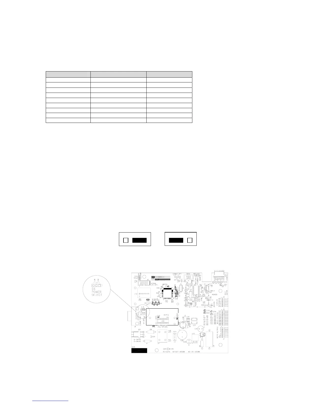
Supply Voltage Jumper (E6)
This allows for a choice in scanner power supply pins and to minimize modifications to a cable or
connector.
Comm port 1 has two pins on the DB 9 connector which provide + 5 volts to supply power to a
scanner. The jumpers located on E6 of the main board will reroute the power (+ 5 volt) to either
pin 9 or pin 4 depending on jumper orientation.
The power (+ 5 volt) and remote key pins are switched. Refer to Figure 1-8 for the jumper
location on the main board. Refer to the Barcode Scanner manual for the power pin location.
Figure 1-8: Comm Port 1 Supply Voltage Jumper Location
Pin 9 (Default) Pin 4