1
Chapter 1: INTRODUCTION
This chapter describes the components of the Model 370/375 such as keypad, enclosure and
display. Also included is wiring for the load cell and communication port.
E
E
n
n
c
c
l
l
o
o
s
s
u
u
r
r
e
e
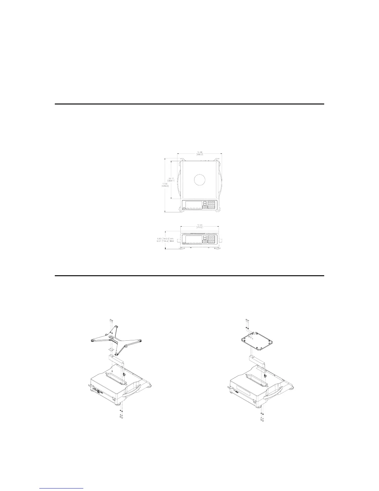
The enclosure is made of die cast aluminum with rib enforcement that includes built in carrying
handles and a line cord wrap for ease of portability. This design provides extra strength and
durability. The enclosure is painted with powder coat and the counting surface is stainless steel.
Figure 1-1: Model 370 and Model 375 Enclosure
L
L
o
o
a
a
d
d
C
C
e
e
l
l
l
l
R
R
e
e
p
p
l
l
a
a
c
c
e
e
m
m
e
e
n
n
t
t
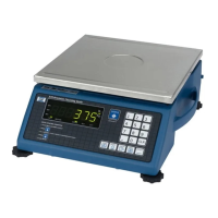
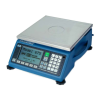
The load cell can be exchanged by removing two M6 1x 20mm (size) bolts from the bottom plate
and two M6 1 x 16mm (size) bolts from the top spider assembly.
Figure 1-2: 15 lb – 100 lb Load Cell Installation Figure 1-3: 6 lb Load Cell Installation