12
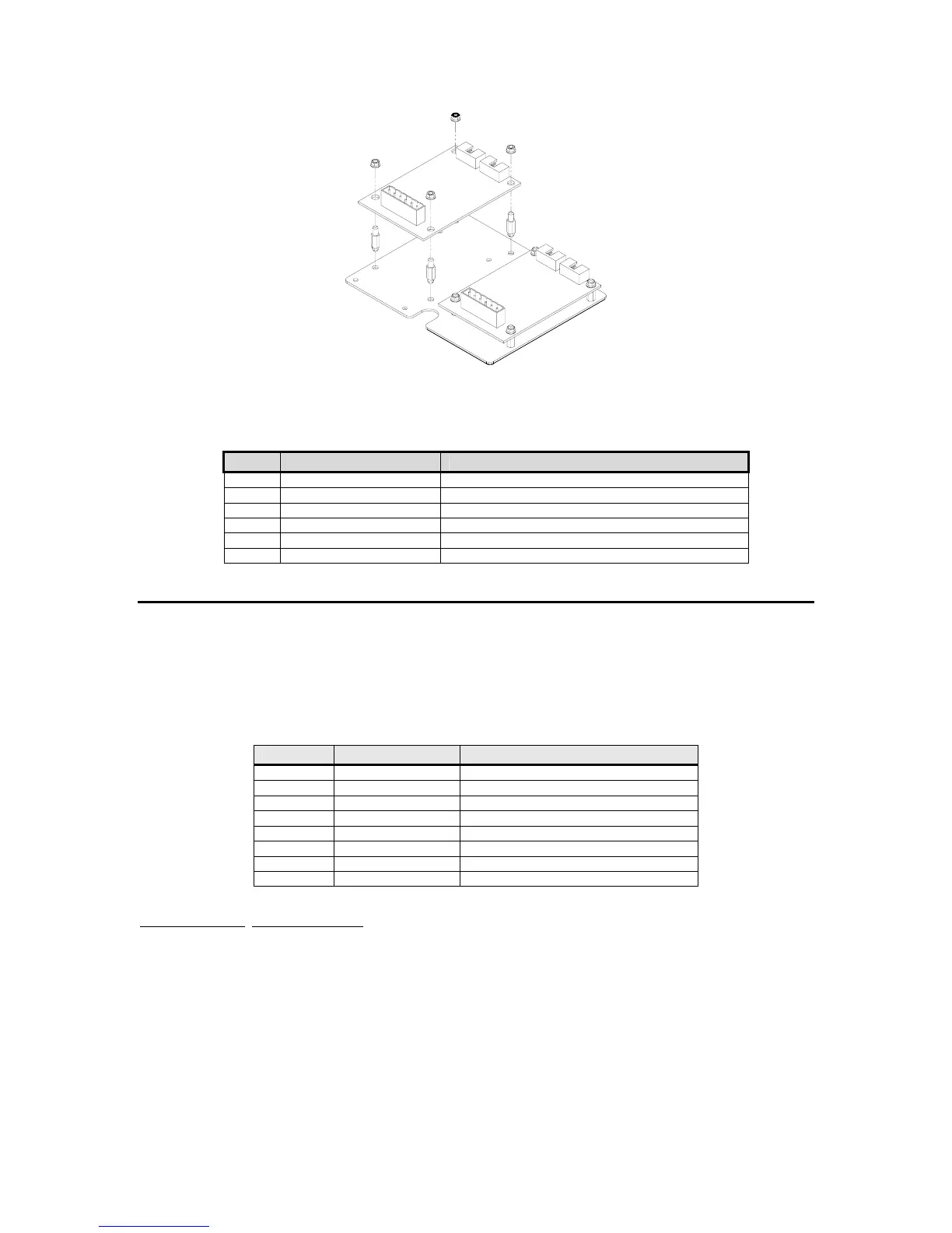
Figure 2-2: Model 370/375 Analog Output and Setpoint Option Installation
Analog Output Connections
Pin Connection Name Description
1 Earth Ground Non-isolated earth ground (future use).
2 + 5 VDC Isolated 5 volt source (future use).
3 Isolated Ground Provides an isolated ground connection.
4 Vout Used for the 0-10 VDC analog signal output.
5 Isolated Ground Provides an isolated ground connection.
6 Iout Used for 4-20 or 0-20 mA analog signal output.
S
S
e
e
t
t
p
p
o
o
i
i
n
n
t
t
O
O
p
p
t
t
i
i
o
o
n
n
The setpoint option provides the ability to running a process, turning on stack lights or anything
else that may require an output signal. Eight different configurations are offered. Requires an
option mounting bracket kit (24370B-300A0) for internal installation.
Table 2-3: Setpoint Option Board Part Numbers
Quantity Part Number Description
1 420925-36594 DC 4 output
1 420926-36589 DC 4 input
1 420924-36584 CD 2/in - 2/out
1 420923-36574 Low voltage AC, 4 input
1 420918-36536 Low voltage AC, 2/in - 2/out
1 420922-36579 AC 4 output
1 420923-37093 High voltage AC, 4 input
1 420918-37092 High voltage AC, 2/in - 2/out
Installation Instructions
1. DISCONNECT POWER! UNPLUG THE MODEL 370/375 TO INSURE DAMAGE WILL NOT
OCCUR DURING OPTION INSTALLATION
2. Remove the (6) 38-31-8710 M5 x 0.8 x 10 mm screws from the enclosure bottom plate and
set it aside.
3. Discard the mounting hardware provided with the setpoint option kit and use the hardware
provided with the option-mounting bracket kit. Refer to page 13 for parts included with this
kit.
4. Snap in the (4) nylon spacers in the 4 holes either to the right of the notch or the left of the
notch in the option mounting bracket.