8
Table 2-1: RS-485 Comm Port 1 Connections
Comm port 1 pin out Connection
1 No connection
2 TX (B+)
3 TX (A-)
4 VCC
5 ISO ground
6 Ground
7 RX (A-)
8 RX (B+)
9 VCC
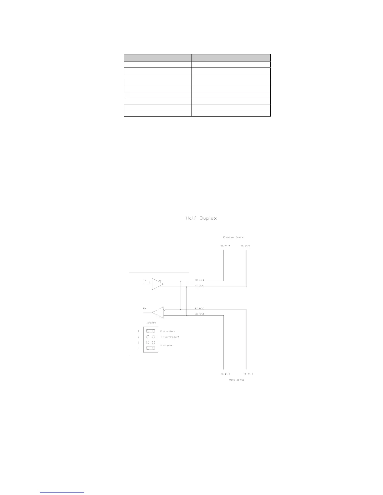
Half Duplex (2-wire)
Installing jumpers 1, 2 and 4 on the RS-485 option board electrically connects pin RX B(+) to pin
TX B(+), and pin RX A(-) to pin TX A(-) on the option board. This effectively provides two + and
two - pin connections, enabling easy connection of network lines in parallel from device to device
without having to position two wires into the same lever socket. A B(+) line from each device on
the network should be connected in parallel to the next device on the network. This is also true for
all A(-) lines.
The units inside the two end-points of the network loop will utilize both A(-) pin connections and
both B(+) pin connections. The units at the end-points of the network will utilize only one A(-) pin
connection and one B (+) pin connection.
Full Duplex (4-wire)
Removing jumpers 1, 2 and 4 on the RS-485 option board requires that the transmit and receive
lines be wired independently of one another. The RX B(+) and RX A(-) receive lines must be
wired in parallel to the next device's RX B(+) and RX A(-) receive lines and the TX B(+) and TX A
(-) transmit lines must be wired in parallel to the next device's TX B(+) and TX A(-) transmit lines.