DA98A AC Servo Drive Unit
User Manual
220
220
PULS+
PULS-
SIGN+
SIGN-
VCC
AC servo drive unit side
Fig. 3.7 Type 3 Single terminal drive mode of pulse volume input interface
(1) Differential drive mode is recommended to be used to transmit pulse data.
(2) AM26LS31, MC3487 or the similar RS422 linear driver are employed in the differential drive
mode.
(3) Action frequency will be reduced in single terminal drive mode. Decide the value of
resistance R according to the pulse input circuit, the 10~15mA drive current and the max.
25V voltage of the external power. Practical data: VCC=24V,R=1.3K~2K;VCC=12V,
R=510~820Ω;VCC=5V,R=82~120Ω.
(4) In single terminal drive mode, the external power supply is provided by user. And if its
polarity is connected reversely, the servo drive unit may be damaged.
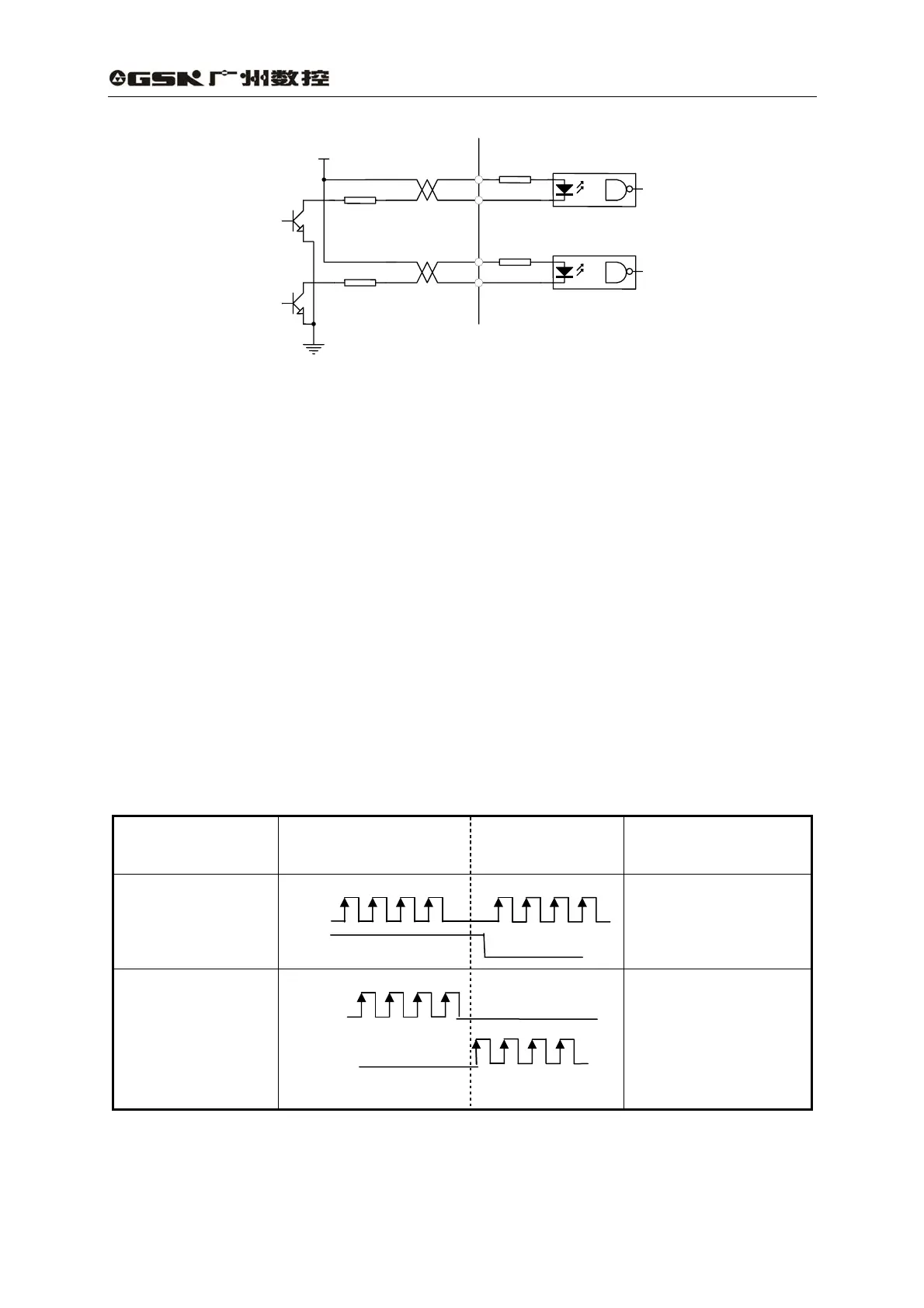
(5) Refer to Table 3.4 about pulse input form, arrowhead represents counting edge, and pulse
input time sequence and parameter are shown in Table 3.5.
Table 3.4 Pulse input form
Pulse instruction
type
CCW CW
Parameter setting
value
Pulse string
Sign string
PULS
SIGN
0
Instruction pulse +
signal
CCW pulse string
CW pulse string
PULS
SIGN
1
CCW pulse /CW pulse
20