DA98A AC Servo Drive Unit
User Manual
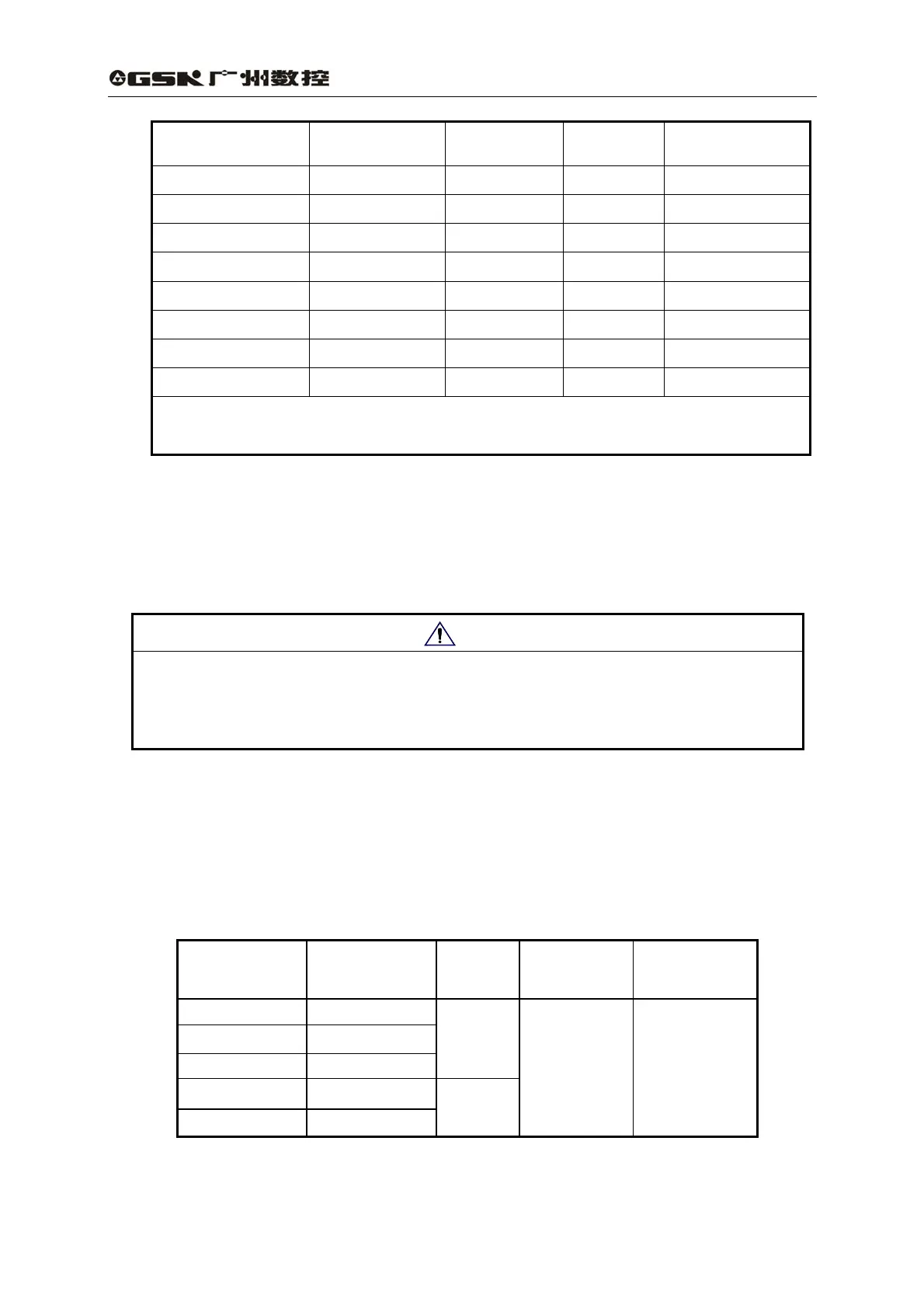
Specification D(mm) N(mm) LB(mm) L(mm)
130SJT—M040D φ22
0
-0.013
φ110
0
-0.035
168 (227) 225 (284)
130SJT—M050D φ22
0
-0.013
φ110
0
-0.035
168 (227) 225 (284)
130SJT—M060D φ22
0
-0.013
φ110
0
-0.035
190 (249) 247 (306)
130SJT—M075D φ22
0
-0.013
φ110
0
-0.035
190 (249) 247 (306)
130SJT—M100B φ22
0
-0.013
φ110
0
-0.035
208 (267) 265 (324)
130SJT—M100D φ22
0
-0.013
φ110
0
-0.035
208 (267) 265 (324)
130SJT—M150B φ22
0
-0.013
φ110
0
-0.035
238 (297) 295 (354)
130SJT—M150D φ22
0
-0.013
φ110
0
-0.035
248 (307) 305 (364)
Note: The values of LB, L in the brackets are the lengths of corresponding
motors with power-down brake.
8.3 Isolation transformer
Note
z It is suggested the AC servo drive unit is powered by isolation transformer to
reduce electric shock or interference by power supply or electromagnetic field.
z The drive unit of 0.8KW or less may be employed with single phase power
supply, but those above 0.8KW must be employed with 3-phase power supply.
The following isolation transformer models are provided by us and they can be
chosen according to the user servo motor power and actual load.
Table 8.5 Isolation transformer specification
Model
Capacity
(KVA)
Phases
Input voltage
(V)
Output voltage
(V)
BS--120 1.2
BS--200 2.0
BS--300 3.0
3
BD--80 0.8
BD--120 1.2
1
380 220
61