DA98A AC Servo Drive Unit
User Manual
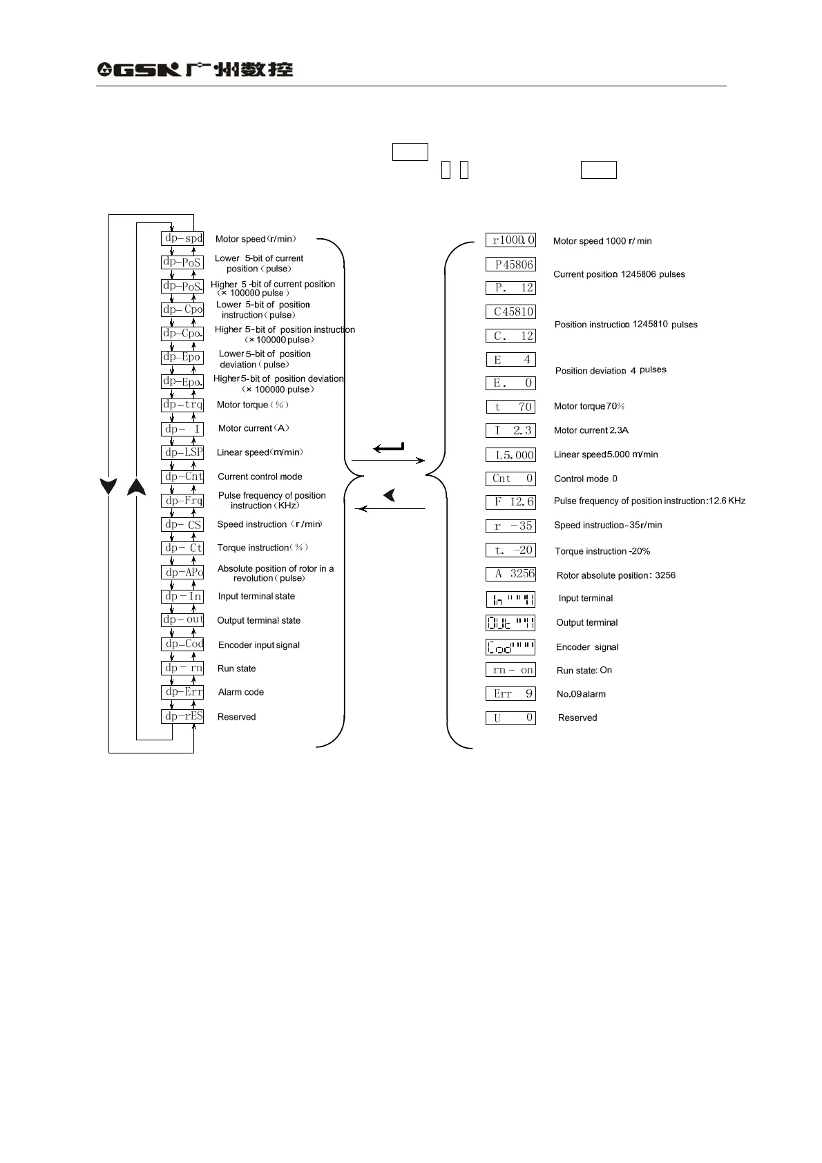
6.2 Monitoring mode
Select “dP-” in the first layer and press Enter to enter monitoring mode which includes 21
display modes. Select the desired display mode by ↑, ↓ key, then press Enter to enter display
mode.
Fig. 6.2 Operation block diagram of monitoring mode
[Note 1] Position pulse and instruction pulse value are the magnified ones via the electronic gear.
[Note 2] Pulses unit is the internal pulse unit that is 10,000 pulses/rev in this system. And it is
expressed by high 5-bit plus low 5-bit and its caculation method is as follows:
Pulses =high 5-bit numerical value×100,000+low 5-bit numerical value
[Note 3] Control mode:0-position control;1- speed control;2- trial speed run; 3- JOG mode;
4- encoder zeroing; 5- open loop run.
[Note 4] If the numerical value displayed has 6 digits (e.g. -12345), the prompt character will not
be displayed.
[Note 5] Before magnified by the electronic gear, pulse frequency of position instruction is the
actual frequency with positive number for positive direction and negative number for
negative direction and its min. unit is 0.1kHz.
[Note 6] Calculation of motor current I is as follows:
43