DA98A AC Servo Drive Unit
User Manual
18
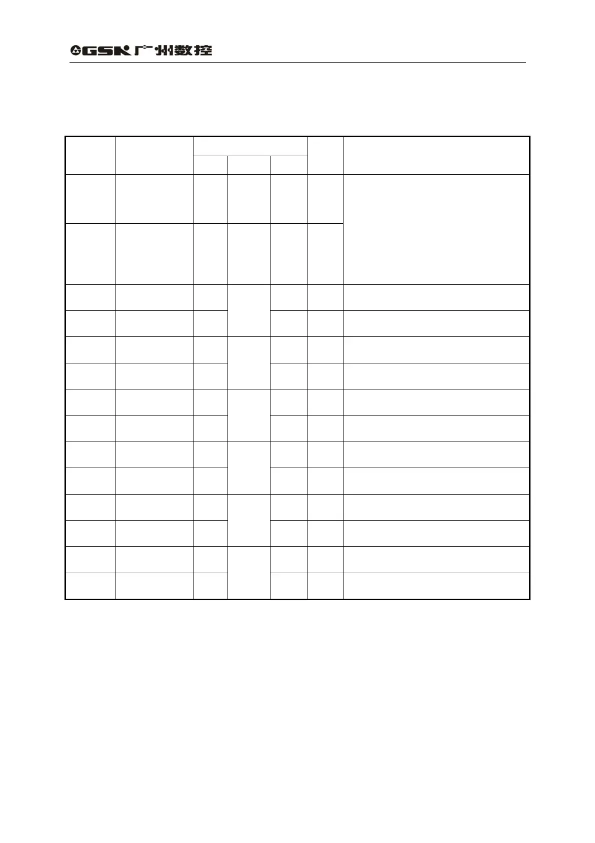
4) Feedback signal terminal CN2
Table 3.3 CN2 input/output terminal of encoder signal
Terminal mark
Terminal
No.
Signal name
Mark I/O Mode
Color
Function
CN2-5
CN2-6
CN2-17
CN2-18
Power supply
output (+)
+5V
CN2-1
CN2-2
CN2-3
CN2-4
CN2-16
Power supply
output (-)
0 V
The servo motor photoelectric
encoder is employed with +5V
power supply; multi-core cable in
parallel are used as the length of
cable is too long.
CN2-24
Encoder (A+)
input
A+
Connecting with servo motor
photoelectric encoder(A+)
CN2-12
Encoder (A-)
input
A-
Type 4
Connecting with servo motor
photoelectric encoder(A-)
CN2-23
Encoder (B+)
input
B+
Connecting with servo motor
photoelectric encoder(B+)
CN2-11
Encoder (B-)
input
B-
Type 4
Connecting with servo motor
photoelectric encoder(B-)
CN2-22
Encoder (Z+)
input
Z+
Connecting with servo motor
photoelectric encoder(Z+)
CN2-10
Encoder (Z-)
input
Z-
Type 4
Connecting with servo motor
photoelectric encoder(Z-)
CN2-21
Encoder (U+)
input
U+
Connecting with servo motor
photoelectric encoder(U+)
CN2-9
Encoder (U-)
input
U-
Type 4
Connecting with servo motor
photoelectric encoder(U-)
CN2-20
Encoder (V+)
input
V+
Connecting with servo motor
photoelectric encoder(V+)
CN2-8
Encoder (V-)
input
V-
Type 4
Connecting with servo motor
photoelectric encoder(V-)
CN2-19
Encoder (W+)
input
W+
Connecting with servo motor
photoelectric encoder(W+)
CN2-7
Encoder (W-)
input
W-
Type 4
Connecting with servo motor
photoelectric encoder(W-)
3.3 I/O Interface principle
1) Input interface of switching volume