2. Set the probe attenuation to x10 on the probe.
3. Connect the probe to the 2V calibration signal.
The calibration signal outputs a 1kHz, 2Vpp
square wave signal.
4. Press the vertical icon.
5. Select CH1, if it is not already selected.
6. Press the option icon.
7. Press Probe and set the probe to 10X.
8. Exit from the Vertical menu (tap anywhere
outside the Vertical menu).
9. Press the Autoset button on the bottom
corner of the screen.
10. The calibration signal is displayed on the
screen.
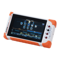
11. Tap the title bar to access the Menu tray.
12. Press Display>Type and select Vector as the
 Loading...
