27
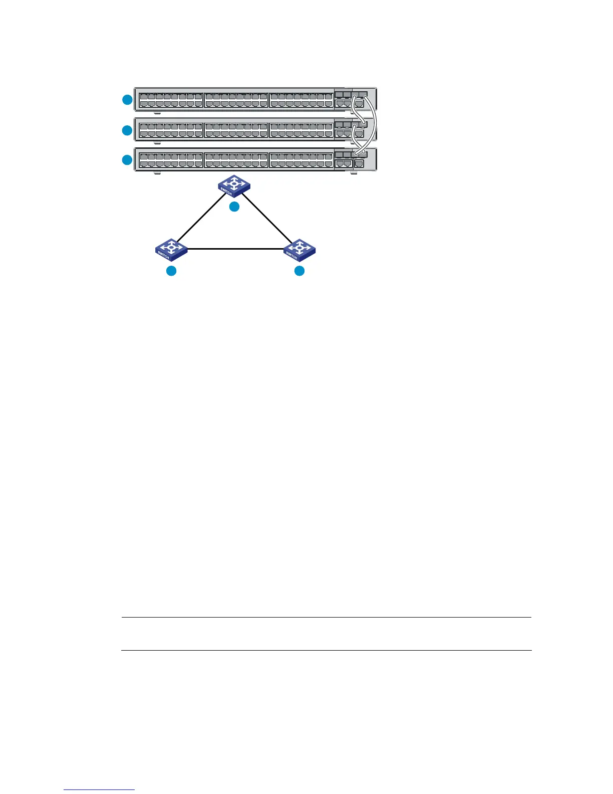
Figure 25 IRF fabric in ring topology
IRF-port1
IRF-port2
IRF-port1
IRF-port1
IRF-port2
IRF-port2
1
2 3
1
2
3
Identifying physical IRF ports on the member switches
Identify the physical IRF ports on the member switches according to your topology and connection
scheme.
When using a combo interface for IRF connection, configure the fiber or copper port of the combo
interface as active. For how to configure the combo interface state, see the H3C S3100V2-52TP Switch
Layer 2—LAN Switching Configuration Guide.
Planning the cabling scheme
Use GE Ethernet twisted pairs, SFP IRF modules or SFP transceiver modules, and fibers to connect the IRF
member switches. If the IRF member switches are far away from one another, choose GE Ethernet twisted
pairs or the SFP transceiver modules with optical fibers. If the IRF member switches are all in one rack,
choose SFP IRF modules.
Table 10
Lists the SFP transceiver modules and SFP IRF modules available for IRF connections.
The following subsections describe several IRF connection schemes and use SFP IRF modules or SFP
transceiver modules with optical cables for example. All these schemes use a ring topology.
Connecting the IRF member switches in one rack
NOTE:
This example uses nine switches.
You can connect the IRF member switches in one rack (see Figure 26), and Figure 27 shows the IRF fabric
topology.

 Loading...


