10
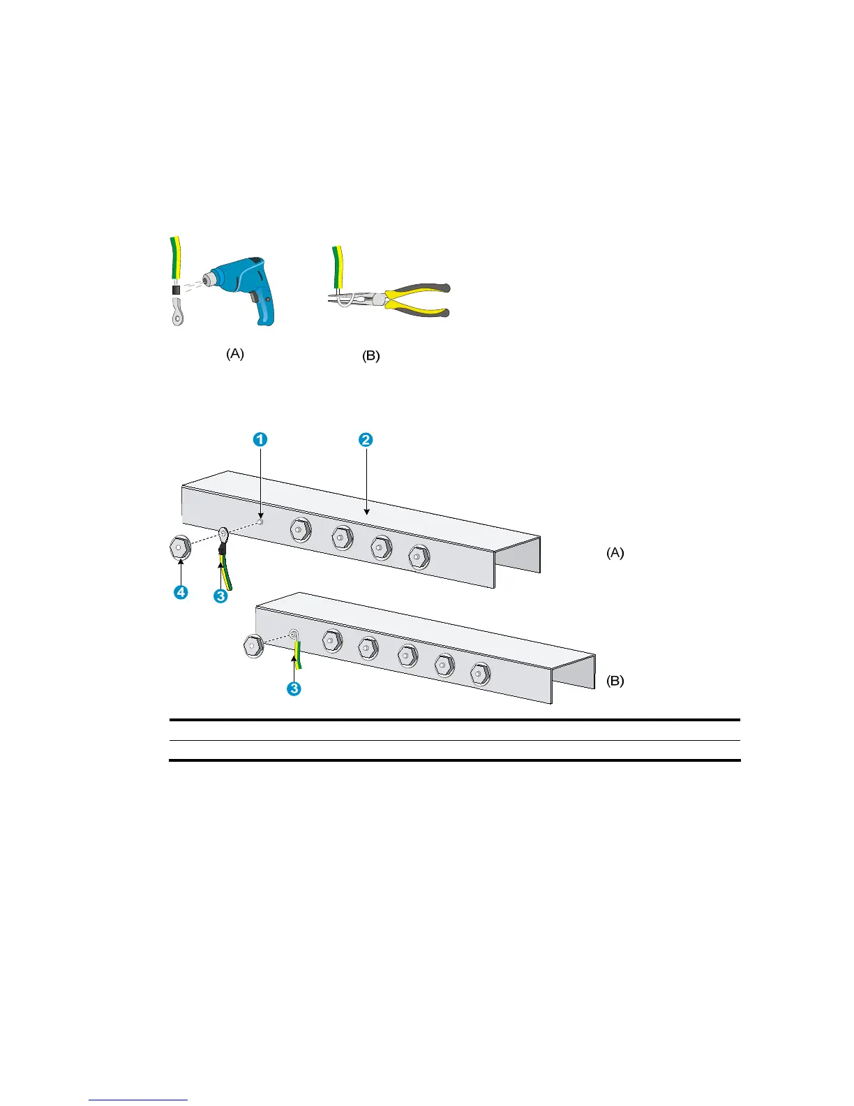
• If you do not have an OT terminal, follow callout B in Figure 10 to make the connector: Peel the
insulation sheath by an appropriate length by using a wire stripper, and then bend the naked metal
part.
Step4 Connect the made connector to the grounding post of the grounding strip, and then fasten it with a hex
nut, as shown in Figure 11.
Figure 10 Make
the grounding cable connector
Figure 11 Connect the grounding cable to a grounding strip
(1) Grounding post (2) Grounding strip
(3) Grounding cable (4) Hex nut
Grounding the switch with a grounding conductor buried in the
earth ground
If the installation site has no grounding strips, but earth ground is available, hammer a 0.5 m (1.64 ft) or
longer angle iron or steel tube into the earth ground to serve as a grounding conductor.
The angle iron must have a dimension no less than 50 × 50 × 5 mm (1.97 × 1. 97 × 0.20 in) and the steel
tube must have a wall thickness no less than 3.5 mm (0.14 in) and be zinc-coated.
Weld the yellow-green grounding cable to the angel iron or steel tube and treat the joint for corrosion
protection.

 Loading...


