system in the equipment room. Do not connect it to a fire
main or lightning rod.
Connecting the grounding cable to the switch
Follow these steps to connect the grounding cable:
Step1 Remove the grounding screw on the rear panel of the switch chassis.
Step2 Attach the grounding screw to the OT terminal of the grounding cable.
Step3 Use a screwdriver to fasten the grounding screw into the grounding screw hole.
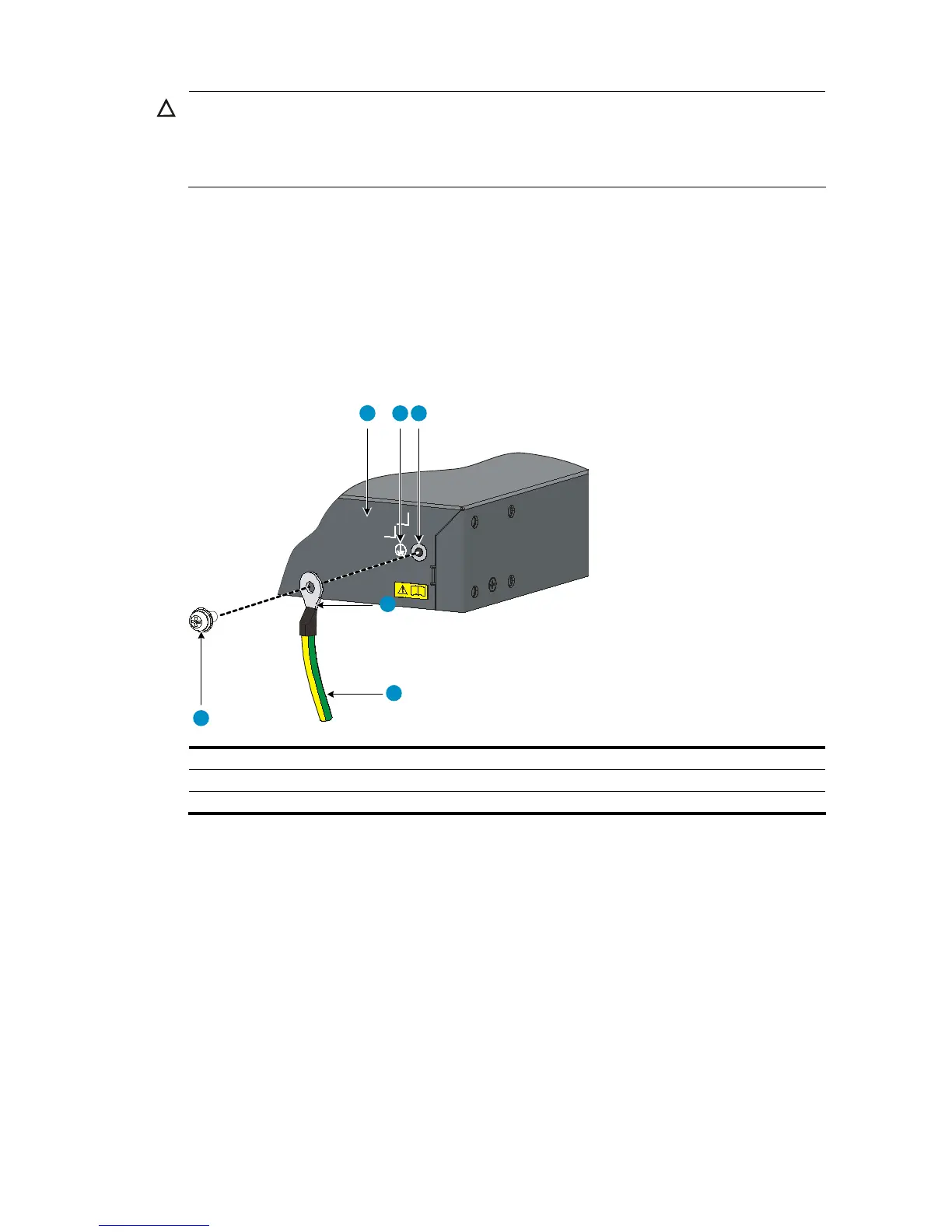
Figure 9 Connect the grounding cable to the grounding hole of switch
6
5
4
1 2 3
(1) Chassis rear panel (2) Grounding sign
(3) Grounding hole (4) OT terminal
(5) Grounding cable (6) Grounding screw
Connecting the grounding cable to a grounding strip
Follow these steps to connect the grounding cable to a grounding strip:
Step1 Remove the hex nut from the grounding strip.
Step2 Cut the grounding cable to a proper length according to the distance between the switch and the
grounding strip.
Step3 Make the connector on the grounding cable:
• If you have an OT terminal, follow callout A in Figure 10 t
o make the connector: Peel 5 mm (0.20
in) of insulation sheath by using a wire stripper, and then insert the naked metal part through the
insulation covering into the end of the OT terminal. Secure the metal part of the cable to the OT
terminal with a crimper, and then cover it with the insulation covering. Then heat the insulation
covering with a blower to make it completely cover the metal part.

 Loading...


