29
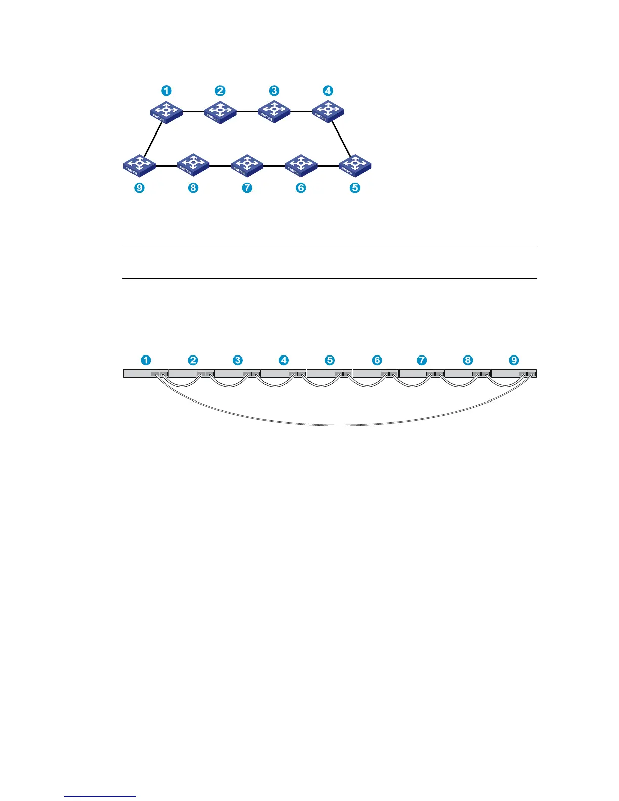
Figure 27 IRF fabric topology
Connecting the IRF member switches in different racks
NOTE:
This example uses nine switches.
You can install IRF member switches in different racks side by side. Figure 28 shows an example for
connecting nine IRF member switches in different racks, and Figure 27 sh
ows the IRF fabric topology.
Figure 28 Connect the IRF member switches in different racks
Configuring basic IRF settings
After you install the IRF member switches, power on the switches, and log in to each IRF member switch
(see the H3C S3100V2-52TP Switch Fundamentals Configuration Guide) to configure their member IDs,
member priorities, and IRF port bindings.
Follow these guidelines when you configure the switches:
• Assign the master switch higher member priority than any other switch.
• Bind physical ports to IRF port 1 on one switch and to IRF port 2 on the other switch. You perform
IRF port binding before or after connecting IRF physical ports depending on the software release.
• Execute the display irf configuration command to verify the basic IRF settings.
For more information about configuring basic IRF settings, see the H3C S3100V2-52TP Switch IRF
Configuration Guide.
Connecting the physical IRF ports
Connect IRF member switches with GE Ethernet cables, SFP IRF modules or SFP transceiver modules, and
fibers as planned.

 Loading...


