2-12
2 Chassis views
LS-6850-56HF/LS-6850-56HF-H1/S6850-56HF-
SAN
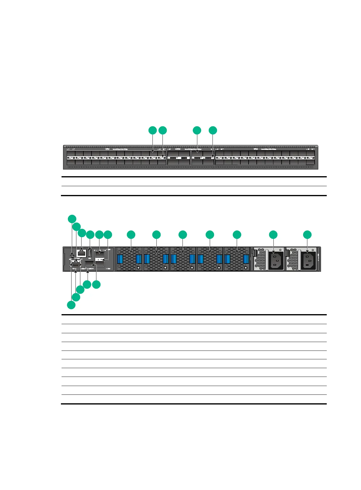
Figure2-1 LS-6850-56HF/LS-6850-56HF-H1/S6850-56HF-SAN front panel
(1) 48 × 1GE/10GE/25GE SFP28 Ethernet fiber ports
(3) 8 × 40GE/100GE QSFP28 Ethernet fiber ports
Figure2-2 LS-6850-56HF/LS-6850-56HF-H1/S6850-56HF-SAN rear panel
(1) Mini USB console port
(2) Copper management Ethernet port (numbered 0)
(5) Two 1GE SFP Ethernet fiber ports
(14) Fiber management Ethernet port (numbered 1)
(15) Fiber management Ethernet port LED (LINK/ACT)
(16) Copper management Ethernet port LED (ACT)
(17) System status LED (SYS)
(18) Copper management Ethernet port LED (LINK)
The LS-6850-56HF, LS-6850-56HF-H1, and S6850-56HF-SAN switches come with power module
slot PWR1 empty and power module slot PWR2 installed with a filler panel. You can install one or two
power modules for the switch as needed. In Figure2-2, two LSVM1AC650 power modules are
installed in the power module slots.
1
2
3
4 5 8
9 10
11 12
13
14
15
16
17
6
7
18

 Loading...


