5-52
LED status Description
cord connection or power source shutdown.
Fan tray alarm LEDs
Each fan tray provides an alarm LED. Table5-14 shows the description for the alarm LEDs on the
FAN-40B-1-C or FAN-40F-1-D fan tray. For the description of the alarm LEDs on other fan trays, see
Table5-13.
Table5-13 Description for the alarm LEDs on the fan trays (1)
Status Description
On The fan tray is faulty.
Off The fan tray is operating correctly or no power is being input.
Table5-14 Description for the alarm LEDs on the fan trays (2)
Status Description
Steady green The fan tray is operating correctly.
Steady red The fan tray is faulty.
Off The fan tray is not installed securely or no power is present.
Power module status LED
The LS-6850-56HF-H3 switch provides a power module status LED (PSU) to indicate the power
module status.
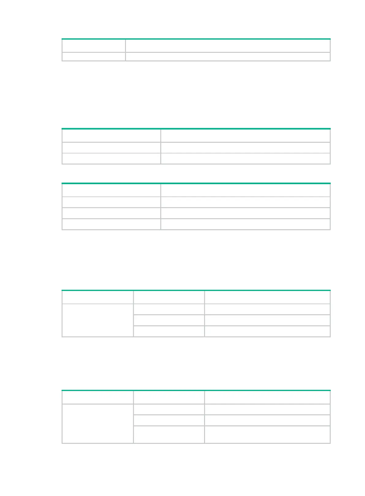
Table5-15 Description for the power module status LED
LED mark Status Description
PSU
Steady green Both power modules are operating correctly.
Steady yellow A power module is faulty or not present.
Off Both power modules are faulty or not present.
Fan tray status LED
The LS-6850-56HF-H3 switch provides a fan tray status LED (FAN) to indicate the fan tray status.
Table5-16 Description for the fan tray status LED
LED mark Status Description
FAN
Steady green All fan trays are operating correctly.
Steady yellow A fan tray is faulty or not present.
Steady red
A minimum or two fan trays are faulty or not
present.

 Loading...


