6-53
6 Cooling system
The chassis and power modules use separate air aisles. Make sure the two aisles are not blocked
when the switch is operating.
To dissipate heat timely and ensure system stability, the switch uses the front-rear air aisle cooling
system. Consider the site ventilation design when you plan the installation site for the switch.
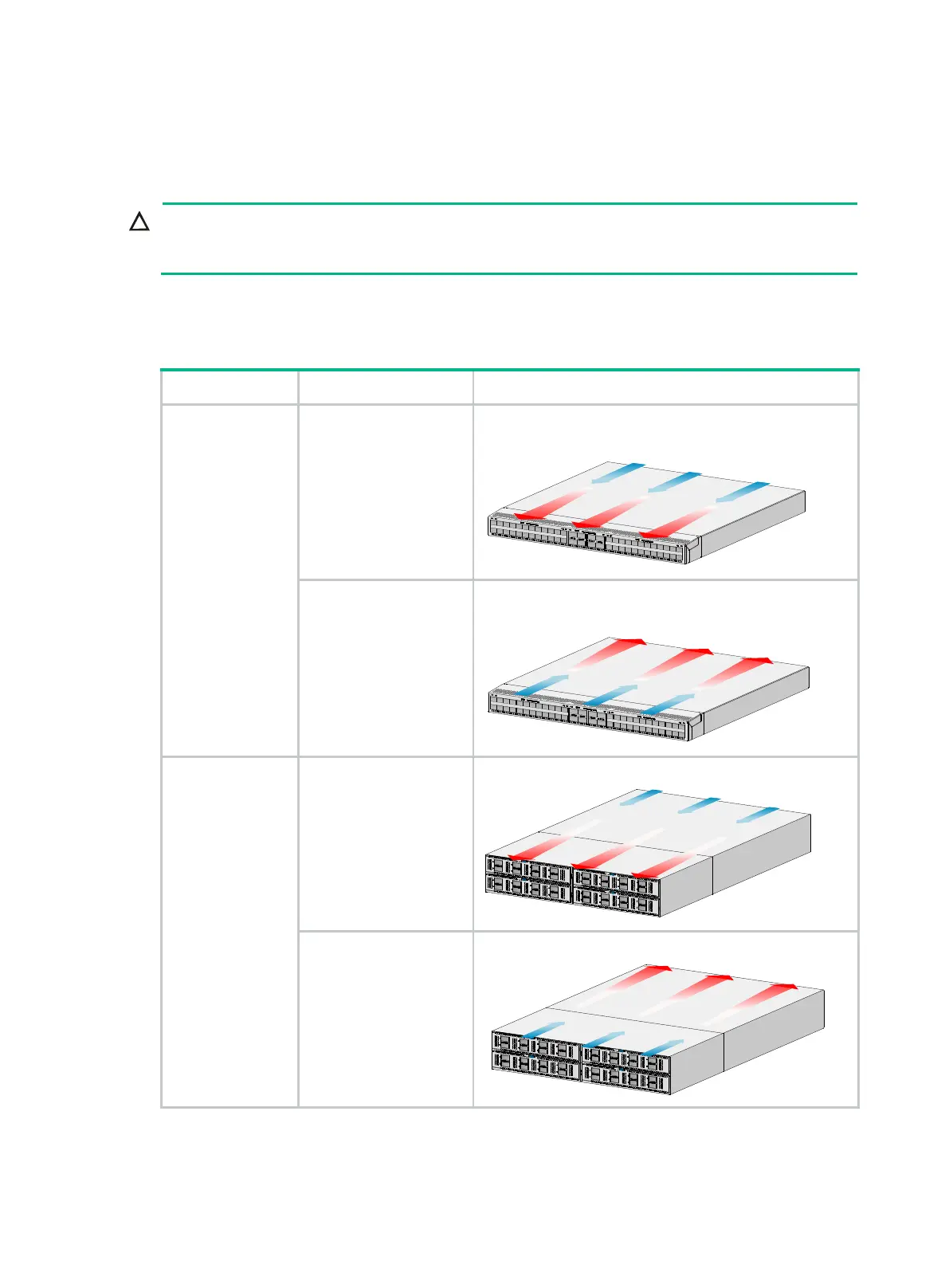
Table6-1 Cooling system for the switch
Switch model Available fan trays Airflow direction
• S6850-56HF
• S6850-56HF-
SAN
• S6850-2C
• S9850-32H
LSWM1FANSA
LSWM1FANSA-SN
FAN-40F-1-D
From the power module side to the port side
The following uses LS-6850-56HF as an example:
LSWM1FANSAB
LSWM1FANSAB-SN
FAN-40B-1-C
From the port side to the power module side
The following uses LS-6850-56HF as an example:
S9850-4C
LSWM1BFANSC
LSWM1BFANSC-SN
From the power module side to the port side
LSWM1BFANSCB
LSWM1BFANSCB-SN
From the port side to the power module side

 Loading...


