4
Table 4 Harmful gas limits in an equipment room
Gas Max. (mg/m
3
)
SO
2
0.2
H
2
S 0.006
NH
3
0.05
Cl
2
0.01
NO
2
0.04
Cooling system
For heat dissipation, make sure the following requirements are met:
• A minimum clearance of 100 mm (3.94 in) is reserved around the inlet and outlet air vents.
• The installation site has a good cooling system.
The firewall adopts either of the following airflow for heat dissipation by installing different fan trays:
• Rear-to-front airflow—The FAN-20F-2-A fan tray blows air from the power module side to the
port side as shown in Figure 1. The fan tray has a bl
ue fan tray handle.
• Front-to-rear airflow—The FAN-20B-2-A fan tray draws air from the port side to the power
module side as shown in Figure 2.
The fan tray has a red fan tray handle.
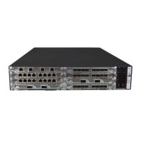
Figure 1 Rear to front airflow provided by the FAN-20F-2-A fan tray
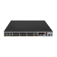
Figure 2 Front-to-rear airflow provided by the FAN-20B-2-A fan tray
ESD prevention
To prevent electrostatic discharge (ESD), note the following guidelines:
• Make sure the firewall and the rack are reliably grounded.