Page 57
5.2.4 System Fuse Specifications
Table 5 below summarizes the location and specification of the fuses used in BioTector. The locations of the
fuses are also displayed in figure 9 above.
Table 5 System Fuse Specifications
Power and
Input/Output
Board
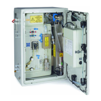
BioTector
Compressor
Start Signal
Cable
KEY
A: Amperes
DIN: German Institute for Standardization (Deutsches Institut für Normung e.V.)
F1-6: Fuse Number
F: Fast Acting (Fast Blow)
H: High Interrupt
ID: Identification
L: Low Interrupt
mA: Milli-amperes
N/A: Not Applicable
PCB: Printed Circuit Board
T: Time Lag (Time Delay)
V: Volts
*1: (Optional) used with TDK power supply, type SWS300-24 only.
*2: (Optional) if higher powered device are connected, for example Multi-channel Modbus / Profibus,
External Valve, External Relay.
BioTector contains electrical components operating under high voltages.
Contact may result in electric shock and severe or fatal injury.
All electrical work should be carried out by qualified electrical personnel only.
When any fuse replacement is required in the system, please refer to table 5
below and system specific drawings.