Do you have a question about the Hach BioTector B7000i and is the answer not in the manual?
Details the meaning and usage of safety signs like Information, Caution, Warning, and Danger.
Summarizes the various precautionary labels found on the instrument and their meanings.
Identifies potential safety hazards associated with the BioTector system.
Outlines general safety guidelines to be observed during operation and maintenance.
Details safety measures related to electrical hazards and hot surfaces.
Provides safety guidelines for handling carrier gas (oxygen) and exhaust gases.
Outlines safety measures when handling chemicals and reagents used with the BioTector.
Discusses precautions to be taken regarding sample streams and potential hazards.
Describes the BioTector's software interface, including menu navigation and screen layouts.
Covers the operation menu for starting and stopping the analyzer.
Details the procedures for starting, stopping, and managing the analyzer's operation.
Describes the procedures for installing and managing reagents.
Provides step-by-step instructions for installing new reagents.
Details how to view and acknowledge logged faults, warnings, and notifications.
Allows the user to calibrate the analyzer via zero and span calibration.
Details the process and options for performing zero calibration.
Explains how to perform span calibration and adjust span factors manually.
Provides a general overview of the BioTector's operation and analysis process.
Outlines the four factory-calibrated analysis types available.
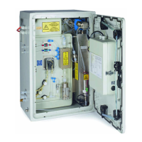
Provides instructions for unpacking and installing the BioTector analyzer.
Explains the procedures for wiring power and signal terminals.
Describes how to connect air supply and reagent lines.
Explains the correct setup and connection of acid and base reagents.
Covers the procedures for connecting sample, drain, and exhaust lines.
Provides information on preparing calibration standard solutions.
Provides access to menu options for diagnostic testing and system checks.
Allows simulation of various process tests like Pressure, Flow, and Ozone.
Enables testing of system devices like pumps, valves, and MFC.
Covers options for selecting communication ports and downloading data.
Provides system service information and counter reset functions.
Used to program system site-specific settings during commissioning.
Sets up multi-stream system parameters like valve sequence and ranges.
Sets up alarm levels and conditions for specific streams and CO2 readings.
Explains fault conditions, their causes, and remedial actions.
Details warning events, their causes, and recommended actions.
Provides a checklist for weekly maintenance tasks.
Offers a recommended checklist for the six-month service.
| Power Requirements | 100 - 240 VAC, 50/60 Hz |
|---|---|
| Parameter | TOC |
| Sample Type | Water |
| Analysis Method | Oxidation |
| Measurement Principle | UV persulfate oxidation with NDIR detection |
| Calibration | Automatic |
| Cleaning Interval | Programmable |
| Communication | 4-20 mA, Modbus, Ethernet, USB |
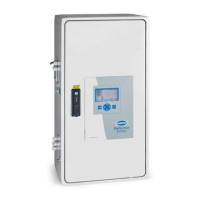
| Display | LCD |
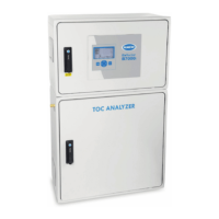
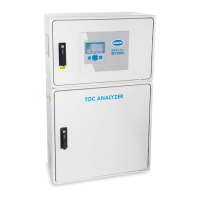
| Enclosure Material | Stainless Steel |
| Operating Temperature | 5-40°C |
| Sample Temperature | 5-40°C |
| Weight | 25 kg |