26
Installation
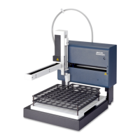
3.4.2 PDS200 connections
Note: Probe speed on existing autosamplers has been reduced to improve performance. The
autosampler may produce a different sound as a result.
To connect the PDS200:
1. Connect the DI Water Line to Port A of the solenoid valve of the dilutor. Place the
other end of the line into the DI water (Figure 23).
2. Connect the Sample Line Assembly to port B of the solenoid valve
(Figure 23, item 3).
3. If necessary, attach the Dual Probe Assembly to the autosampler. The probe guide
may need to be rotated to accommodate the dual probe.
4. Connect the probe sample line (attached to the bent tube of the Dual Probe
Assembly) to port C of the solenoid valve (Figure 23, item 5).
5. Make sure the ferrule on the line from the straight tube of the Dual Probe Assembly is
flush with the end of the tubing (Figure 23, item 2).
6. Insert the connector from the straight tube of the Dual Probe Assembly into port D of
the dilutor (Figure 24 on page 27) and tighten.
7. Make sure the ferrule on the dilutor end of the Diluent Line Filter Assembly is flush
with the end of the tubing (Figure 23, item 2).
8. Insert the connector from the Diluent Line Filter Assembly into port E of the dilutor
and tighten (Figure 23, item 3).
9. Insert the filter end of the Diluent Line Filter Assembly into the diluent (Figure 23,
item 2).
Figure 23 Tubing connectors and ferrule placement
1 Ferrule 4 To DI water port A
2 Flush 5 To sample probe line port C
3 To pump/analyzer port B
 Loading...