15
Installation
3. Place the glass weight end of the waste line in a proper waste container. Never
submerge the waste line in the waste solution because this may cause back pressure
and flow restrictions. Make sure the waste solution always drips into the container.
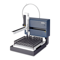
3.1.6 Manifold installation
The manifold is the reaction module where the chemistry occurs.
Specific installation requirements are detailed in the Figure 28 on page 32 included with
each chemistry method. Refer to Figure 11 on page 16 and the following steps to install
the manifold for flow injection analysis.
To install the manifold:
1. On the valve, connect port 1 to port 4 with the sample loop.
2. Connect the manifold outlet to the flow cell inlet (Figure 11 on page 16, item 6).
3. Install the interference filter (Figure 11 on page 16, item 5).
4. Connect the carrier line to port 2 on the valve (Figure 11 on page 16, item 8).
5. Connect the tubing from port 3 to the connector labeled From Valve.
6. Attach one end of a waste line to the flow cell outlet. Drop the other end into a waste
container (Figure 11 on page 16, item 4).
Figure 10 Flow injection connections
1 System unit 5 Waste lines
2 Channel 1 6 Waste container
3 Channel 2 7 Waste line
4 Channel 3 8 Sample line
 Loading...