14
SECTION 1, continued
1.2 Principle of Operation
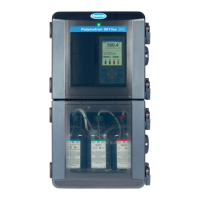
The Hardness Monitor uses a buffered colorimetric hardness indicator solution
that is mixed with the water sample as it flows through the instrument. While in
the colorimeter sample cell, light is transmitted through the solution to a detector,
which provides the colorimetric measurement.
Note: The Class 1 Light Emitting
diode (LED) used as the light source
for the photometric measurement
does not present any potential for
eye damage.
Indicator solutions are formulated to provide 50% transmittance (%T) to the
detector at their nominal alarm point values. Below 50%, the color of
sample/reagent mixture is blue. As hardness increases, the color becomes red.
Because the light source for the colorimetric measurement is an orange light-
emitting diode, a blue solution blocks light to the detector while a red solution
allows light to be transmitted unattenuated through the measurement cell to the
detector. Maximum light transmittance through the cell occurs when all of the
indicating reagent available has reacted with sample hardness and any further
increasing levels of hardness have no effect on solution color.
A linear, peristaltic pump/valve controls the flow of incoming sample and injects
metered volumes of the buffer and indicator reagents on a sequenced cycle. The
pump/valve uses a motor-driven cam to operate pinch blocks that squeeze special
thick-walled tubing against a fixed plate, the sequence operates as follows:
1. The sample inlet line opens and remains open to allow sufficient sample
flow to purge the inlet line and measure cell. While the inlet sample is
flowing, the reagent inlet valve and pinch blocks are opened, filling the tubing
with reagent.
2. The sample inlet line is then pinched shut, leaving a fresh sample in the
measuring cell. The cell volume is controlled by an overflow weir.
3. Reagent inlet valve block is then closed.
4. Reagent outlet valves open and the pinch block squeezes the tubing, forcing
reagent into the measuring cell. A magnetic stirrer mounted beneath the
measuring cell mixes sample and reagent in the cell. Sufficient time is allowed
for sample and reagents to react.
5. An optical interrupter circuit on the drive motor shaft signals the monitor
electronics to take a measurement.
This cycle is repeated approximately every 2 minutes.
 Loading...

