SECTION 2, continued
31
2.9 Installing Pump/Valve Pinch Plate
To eliminate the effects of constant pressure on the pump tubes during shipment
and storage, the pinch plate and screws for the pump/valve module are shipped in
the accessory kit and the pump tubes are held in place with tape.
Reagent flow through the pump/valve module must be from bottom to top. If
reversed, fluid mixture will be pumped from the colorimeter sample cell, causing
reagent bottles to overflow.
Complete the assembly of the pump/valve module as follows:
1. Remove the tape.
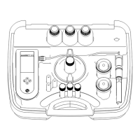
2. Make sure the individual pinch blocks are positioned as shown in Figure 14
with the dissimilar-shaped block on top.
3. Align the pinch plate on the pump/valve module (refer to Figure 15).
4. Install the two screws through the pinch plate and into the pump/valve
module. When securing the pinch plate, advance the screws in small
increments moving from one screw to the other so that the plate is drawn
down evenly. Tighten until snug, do not overtighten.
Figure 14 Installing Pump/Valve Module Pinch Blocks

 Loading...