Design and layout of the device
4 Design and layout of the device
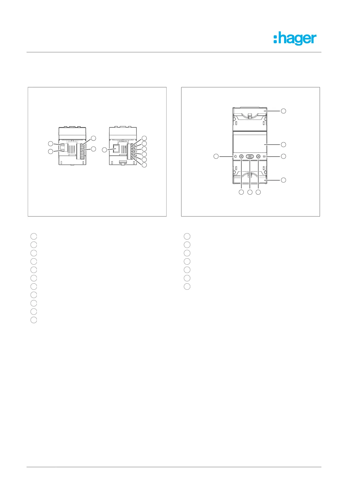
Fig. 2: View of the connecting terminals
1
R1, trip relay, channel 1 (NO)
3
C1, GND channel R1
9
A1, power supply L
11
A2, power supply N
19
Pre-alarm, digital output (NO)
20
GND pre-alarm, digital output
21
TRIP, input for external trigger
22
GND for RS-485 and TRIP input
23
B-, RS-485 interface
24
A+, RS-485 interface
25
RJ45 connector contact for the current transformer
connection
Fig. 3: Front view
12
Cover for connecting terminals
13
CPU LED
14
T button
15
Menu button
16
R button
17
Alarm LED
18
LCD screen
8 Fehlerstromschutz-Relais