30
Operation
Indicator field
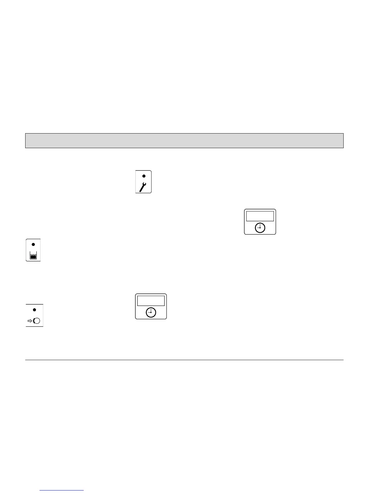
(Fig. 16/1) The indicator field enables
the Hakomatic B1050 to provide feed-
back on the operating status of the ve-
hicle. This only relates to operating
states which cannot be switched on and
off via the operating panel: recovery
tank full, parking brake applied and er-
ror messages.
The individual buttons and functions are
de
scribed in detail below:
Indicator for recovery tank
maximum fill level
(Fig. 16/2) The yellow control
lamp lights up when the recov-
ery tank has reached its maxi-
mum fill level. Also, a "beep" signal is
issued every 15 seconds. In this case, a
float switch switches the suction turbine
off and the squeegee is raised.
Indicator for parking brake
applied
(Fig. 16/3) The control lamp
lights up red when the parking
brake has been actuated via
the pedal to the left of the steering col-
umn. If the traction drive is switched on,
an acoustic signal is also issued.
Indicator for function faults
(Fig. 16/4)
The control lamp lights up red
when
one of the following
faults occurs:
• The thermostatic switch disconnects
fr
om the brush or hydraulic motor.
• One of the safety fuses is defective
or an el
ectronic fuse has been
tripped.
• Another fault has occurred.
At the same time, a four-digit code ap-
pears in the display of the service indi-
cator (Fig. 16/5). This error code infers
which fault has occurred (refer to Sec-
tion 3.5.1). At the same time, the control
lamps flash and an acoustic, pulsating
signal is issued.
Operating hour coun-
ter
(Fig. 16/5) The four-digit
LED serves to display
the operating hours.
When the key in the key switch is turn
on, one and then two four-digit codes
appear in succession (for further de-
tails, refer to Page 34, key switch
(Fig. 17/1). The operating hours appear
after this.
The counter only operates when con-
sumers are switched on (e.g. hydraulic
or brush motor, suction turbine). At the
same time, a red dot flashes at the bot-
tom right of the display.
Service indicator
(Fig. 16/5) The same
LED
also serves for a
more accurate determi-
nation of function faults.
If a fault occurs during operation, a four-
digit code (error code) appears in the
service indicator display. At the same
time, the four dots of the error code
flash in the display and a pulsating
acoustic signal is issued. The control
lamp in the functional fault display lights
up red. Section 3.5 provides an over-
view of the error codes which help you
clear functional faults yourself. Clear
the fault before starting to use the ma-
chine again. If you cannot clear the fault
yourself, note down the error code and
inform the authorized Hako dealer re-
sponsible for your machine.