Do you have a question about the Hardi HC5500 and is the answer not in the manual?
| Type | Sprayer Controller |
|---|---|
| Brand | Hardi |
| Category | Controller |
| Model | HC5500 |
| Manufacturer | Hardi |
| Power Supply | 12 V DC |
| Protection Rating | IP65 |
| Communication | CAN bus |
Statement of conformity with EU directives and harmonized standards.
Guidelines and warnings for safe operation and user protection.
General precautions and recommended practices for safe equipment use.
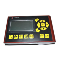
Overview of the HARDI Controller 5500 and its applications in agriculture.
Definitions of technical terms and explanation of symbols used in the manual.
Explanation of the LookAhead system for improved application precision.
How pressure-based regulation functions as an alternative to flow-based.
Description of steering mechanisms for sprayer stability and precision.
Overview of the system components and their interconnections.
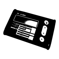
Description of the controller's buttons and their functions.
Illustrates common keystrokes and display interactions for menu navigation.
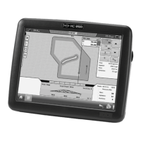
Visual representation of the controller's menu structure and navigation paths.
Guidance on finding a suitable place for control units in the tractor cabin.
Requirements for connecting the 12-15 Volt DC power supply and fuse recommendations.
Location, type, and adjustment of the speed transducer on the sprayer wheel.
Connecting speed sensors from tractor gearbox or radar/GPS to the controller.
Steps for initial power-up, including connecting plugs and setting date/time.
Sequence of information display during controller boot-up.
Procedure for selecting nozzles when LookAhead or pressure regulation is enabled.
Procedure to verify pressure regulation response when sprayer speed changes.
Procedure to verify pressure regulation response when boom sections are opened/closed.
Selecting nozzles and minimum pressure for pressure-based regulation.
Instructions on how to change and read the volume rate setting.
Procedure for changing and displaying the tank contents.
How to read, reset, and change the active register for data logging.
General information on customizing display readouts for various functions.
Configuration of automatic functions like Main ON/OFF and Foam Marker.
Enabling Variable Rate Application (VRA) and remote control inputs.
Procedure for setting the system's date and time for accurate data logging.
Configuration options for various system alarms like volume rate and tank contents.
How to name and copy registers for better data organization.
Process for calibrating speed sensors (Sprayer, Tractor, Radar).
Methods for calibrating the flow transducer, including theoretical and practical.
Settings related to boom configuration, including width and sections.
Adjusting sensitivity of the pressure regulation valve for stability.
Information and calibration for the HARDI Tank Gauge system.
Setup and adjustment of the track system for sprayer steering.
Calibration procedure for the LookAhead feature when using specific nozzles.
Using the electronic trip meter to measure distance and calculate area.
Overview of programmed service intervals and nozzle check reminders.
Using the controller's stopwatch functionality as a timer.
Setting the controller to trigger an alarm at a specific time.
Testing various transducers like flow and speed sensors for proper function.
Using speed simulation for testing purposes, with valid state until restart.
Emergency operation mode that bypasses sensors for manual control.
Options for printing register data, all registers, or controller configuration.
Procedure for dumping data to an office printer using Hyper Terminal.
Explanation of UCR as a calibration method based on canopy dimensions.
Setting up the controller for mistblower UCR and adjusting canopy measures.
Guidance on disconnecting power and protecting the controller during storage.
Operating the control unit without the controller in case of faults.
Table of common operational faults, probable causes, and remedies.
Table of mechanical faults, probable causes, and control/remedy actions.
Formula and method for fine-tuning the flow transducer PPU.
Procedure for testing the flow transducer using a multimeter.
Procedure for testing the speed transducer using a multimeter.
Key technical specifications including voltage, temperature, and memory.
Table listing flow ranges and PPU values for different flow housings.
List of supported baud rates for external communication via RS232.
Information on disposal of electronics and recycling of materials.
Template for logging calibration and constant values.