MODEL M6 13
OPERATIONAL PROCEDURE
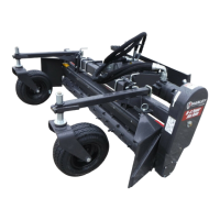
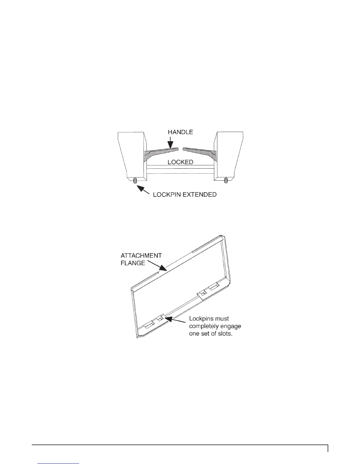
Move the skid-steer coupler handles to the locked position. The lockpins must be completely
extended and secured into the slots provided on the power rake, see Figure 4 and Figure 5
below.
Connect hydraulic hoses to skid-steer auxiliary quick couplers.
For hydraulic angling models, mount the angle control switch in a convenient, easy-to-reach
location. The switch bracket is magnetic and will attach to any at steel surface. Connect the
power cord to the cable coming from the switch. Be careful when routing the cable that sharp
edges or moving parts will not damage the cable.
Figure 4. Skid-Steer Coupler Handles - Locked
Back View of Attachment
Figure 5. Back of Attachment - Slot Locations
POWER RAKE FUNCTION
The power rake hydraulic motor drives the roller, which digs into the ground, cultivating and pulling
up rocks, roots, and debris.
The clean soil goes between the roller and barrier, while the rocks, roots, and debris work to the
side in a windrow.
With the endplates mounted in the working position and the rake straight (endplates parallel with
skid-steer tires), material can be moved along, lling in the low spots. Also, rocks, roots, and
debris can be collected and moved to another location for hauling away.