26 MODEL M6
ASSEMBLY/PARTS IDENTIFICATION
SET-UP INSTRUCTIONS
The power rake is shipped partially assembled. Assembly will be easier if components are
aligned and loosely assembled before tightening hardware. Recommended torque values for
hardware are located on page 4.
Select a suitable working area. Refer to illustrations, accompanying text, parts lists, and ex-
ploded view drawings.
For reference, front, back, left and right directions are determined by sitting in the prime mov-
ers operator’s seat.
It is advisable to have a mechanical lifting device to facilitate uncrating.
UNPACKING CRATE
Be careful of nails in boards when uncrating.
1. Remove top, sides, and ends of crate.
2. Remove attachment plate.
3. Remove gauge wheel assemblies.
4. Remove right and left endplates.
5. Remove rake assembly form crate.
6. Remove loose nails from boards and dispose of crate according to local codes.
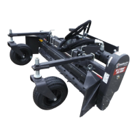
STRAIGHT MODEL ASSEMBLY PROCEDURE (See Figure 10)
Tools Required
15/16” combination wrench
1. Stand rake frame upright and position one endplate on each side of frame to stabilize
the rake.
2. Attach the two gauge wheel assemblies to main frame using two 5/8” U-bolts and lock-
ing nuts as shown in Figure 10 (page 28) and Figure 15 (page 40).
3. Position the attachment mount plate on the frame and clamp in place with four 5/8” U-
bolts and locking nuts.
4. Check the oil level in the chain case. If needed, add #00 uid gear grease. See in-
structions near ll/vent plug, Figure 15 (page 40).
 Loading...