MODEL M6 27
ANGLING MODEL (NON-FLOAT) ASSEMBLY PROCEDURE
(See Figure 11 & Figure 15)
Tools Required
15/16” combination wrench
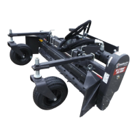
1. Stand rake frame upright and install endplates on attachment side of frame to stabilize.
2. Attach the two gauge wheel assemblies to main frame using two 5/8” U-bolts and lock-
ing nuts as shown in Figure 11 (page 30) and Figure 15 (page 40).
3. Install power cord by connecting the red clamp to a positive 12 volt power source and
the black clamp to ground. The power cord includes an in-line fuse and spring-loaded
battery clamps. The red (positive) cable is fused and should always be connected to
the positive side of the battery to ensure proper operation of the electrical circuit. Be
careful when routing the cable that sharp edges or moving parts will not damage it.
4. Check the oil level in the chain case. If needed, add #00 uid gear grease. See instruc-
tions near ll/vent plug, Figure 15 (page 40).
ANGLING MODEL (WITH FLOAT)
(See Figure 13 & Figure 15)
Tools Required
15/16” combination wrench
1. Raise front of rake up so pivot frame is horizontal.
2. Mount left and right endplates.
3. Move attachment mounting plate into position.
4. Attach four link arms to the attachment plate (lower arms rst).
5. Tighten nuts after all four arms are in place.
6. Replace the 3/4” X 4-3/4” pins in either the “lockout” or “oat” positions.
7. Attach the two gauge wheel assemblies to main frame with two 5/8” U-bolts and Locking
nuts as shown in Figure 11 (page 30) and Figure 15 (page 40).
8. Check the oil level in the chain case. If needed, add #00 uid gear grease. See instruc-
tions near ll/vent plug, Figure 15 (page 40).
ASSEMBLY/PARTS IDENTIFICATION