SERVICE PROCEDURE
ALIGNMENT PROCEDURES
1.MAIN AMP idling Adjustment
SET CONDITION
1) SEMI VOLUME POSITION at MAIN/SURROUND AMP Board
MAIN:VR71.VR72
SURROUND:VR73.VR74
NO Signal/No Load
AC Line Voltage:120V/60Hz.230V/50Hz
2) After turning on the unit keep it over than 25min (keep the power/Driver TR as normal temperature)
3) Adjust the voltage value of primary&secondary of wafer to be 25mV by rotating the semi volume of each channel
to the right
CHANNEL ADJUSTMENT MEASUREMENT VOLTAGE
FRONT-L CH VR71 P817 23+/-2mV
FRONT-R CH VR72 P805 23+/-2mV
SURROUND-L CH VR73 P818 23+/-2mV
SURROUND-R CH VR74 P806 23+/-2mV
4) CAUTION
In case that power TR or DRIVER TR is needed to be replace for repairing the corresponding channel should be
adjusted again
FRONT AMP:Q437.Q433.Q435.Q439.Q438.Q434.Q436.Q440
SURROUND AMP:Q333.Q329.Q331.Q335.Q334.Q330.Q332.Q336
2.SURROUND BACK AMP idling Adjustment
SET CONDITION
1) SEMI VOLUME POSITION at CENTER/SURROUND BACK AMP Board
CENTER:VR501
SURROUND BACK:VR201.VR301
NO Signal/No Load
AC Line Voltage:120V/60Hz.230V/50Hz
2) After turning on the unit keep it over than 25min (keep the power/Driver TR as normal temperature)
3) Adjust the voltage value of primary&secondary of wafer to be 25mV by rotating the semi volume of each channel
to the right
CHANNEL ADJUSTMENT MEASUREMENT VOLTAGE
CENTER VR501 P501 23+/-2mV
SURR BACK-L CH VR201 P201 23+/-2mV
SURR BACK-R CH VR301 P301 23+/-2mV
4) CAUTION
In case that power TR or DVIER TR is needed to be replace for repairing the corresponding channel should
be adjusted again
CENTER AMP:Q519,Q517.Q516,Q518
SUR BACK AMP:Q319.Q317.Q316.Q318.Q219.Q217.Q216.Q218
3.Cautions for main adjustment
1) At MAIN/SUPPLY BOARD.use the below capacitor after discharging for sufficent time for preventing
possible damage from electrical spark
MAIN C571.C572 AVR745/645 15000/63V
BOARD C571.C572 AVR445 12000/63V
SUPPLY C201,C202 AVR745/645 10000/63V
BOARD C201,C202 AVR445 8200/63V
2)The checking for MAIN/SUPPLY BOARD should have the discharging circuit discharge
over 30sec.through(4R7Ohm 10W)resistor after push power sw off
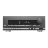
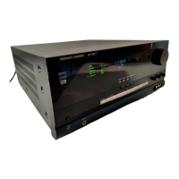
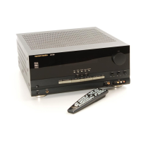
AVR745
harman/kardon
 Loading...