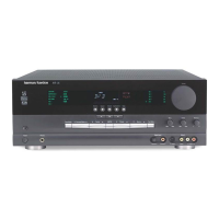


Do you have a question about the Harman Kardon AVR 745 and is the answer not in the manual?
| Brand | Harman Kardon |
|---|---|
| Model | AVR 745 |
| Category | Receiver |
| Language | English |
Detailed audio performance specifications including power, sensitivity, and frequency response.
Specifications for the AM tuner, including frequency range and sensitivity.
Technical specifications related to video input and output formats.
Overall product dimensions, weight, power requirements, and feature details.
Diagram illustrating the layout of components within the product packaging.
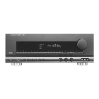
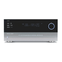
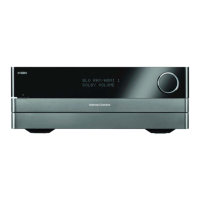
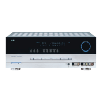
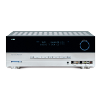
Detailed explanation of front panel controls, buttons, display lines, and indicators.
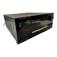
Description of controls and jacks accessible behind the front-panel door.
Diagram and list of all rear panel connection terminals with their functions.
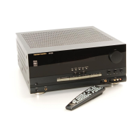
Identification of buttons and features on the TC 30 remote control.
Detailed descriptions of how each button on the TC 30 remote operates.
Identification of buttons and features on the ZR 10 remote control.
Detailed descriptions of how each button on the ZR 10 remote operates.
Initial system setup and guidelines for connecting audio sources and recorders.
Instructions for connecting analog video sources like VCRs and DVD players.
Details on connecting the AVR 745 via HDMI, including version compatibility.
Connecting external control components, power amplifiers, and power cords.
Options for sending audio signals to a remote zone using various connection methods.
Methods for sending video signals to a remote room location.
Connecting the AVR 745 to compatible A-BUS/READY products for remote zone operation.
Guidance on connecting the AVR 745 for external computer or control system integration.
Instructions for connecting computers or media players via USB for playback and updates.
Using low-voltage triggers to control compatible optional devices.
Steps for connecting and setting up an XM Radio module for satellite radio.
Information on using the switched AC accessory outlet and power cord.
Procedures for powering the unit on, off, and using sleep mode.
Methods for choosing input sources from the front panel, TC 30, or ZR 10 remote.
Adjusting volume, muting, and controlling bass/treble settings.
How to choose and apply different surround sound modes.
Understanding and utilizing digital audio sources like Dolby Digital and DTS.
Details on the DTS digital audio format and its playback compatibility.
Steps for configuring and selecting digital audio inputs.
Connecting and playing audio from a computer via the USB port.
Interpreting digital bitstream information and channel indicators.
Interpreting front-panel indicators for speaker configuration and signal status.
Using the Night Mode feature to reduce dynamic range for late-night listening.
Default digital format for DVDs and ATSC high-definition systems.
Tuning and selecting stations for AM and FM broadcasts.
Adjusting video settings and using the Faroudja processing features.
Setting up and operating the XM Radio service for satellite radio.
Storing and recalling radio stations into memory presets.
Manually adjusting speaker output levels for optimal sound balance.
Using the automated speaker setup and EQ system for acoustic optimization.
Managing subwoofer output, including turning individual subwoofers on/off.
Adjusting the brightness of the front-panel displays and indicators.
Understanding the system's memory backup and configuration preservation.
Table listing common symptoms, their potential causes, and solutions.
Procedure to reset the AVR 745's memory and configuration settings.
Procedure for adjusting idling current on the main amplifier board.
Procedure for adjusting idling current on the surround back amplifier board.
Important safety precautions and notes before performing main adjustments.
Description of key processing and digital interface ICs within the AVR 745.
Details on the DSP, memory, and audio output stages of the AVR 745.
Detailed block diagram of the audio signal processing and amplification sections.
Block diagram illustrating the video signal processing and interface circuits.
Pinout definition for the uPD70F3261YGC microcontroller used in the AVR745.
Detailed list of IC pin names, their input/output functions, and descriptions.
Top-side layout diagram of the main printed circuit board.
Bottom-side layout diagram of the main printed circuit board.
Layout diagrams for various other PCBs within the AVR 745 unit.
List of capacitors, semiconductors, and resistors for the DSP PCB.
Components for RS232 PCB, Standby PSU, Surround PCB, and Video PCB.
List of miscellaneous mechanical and connector components.
List of components for the tuner modules (USA and Europe).
Schematic diagram detailing the front panel circuitry and controls.
Schematic diagram of the main amplifier section of the AVR 745.
Part one of the processor schematic, illustrating the DSP and related circuits.
Part two of the processor schematic, detailing further processor and interface circuits.
Schematic diagram illustrating the RS232 communication interface.
Schematic diagram of the power supply unit for the AVR 745.
Schematic diagram for the center and surround back amplifier boards.
Detailed schematics of the DSP section, broken down into four parts.
Schematics detailing the video processing and interface circuitry.