TEC0020 2018JAN3 P/N: 630-00025 Rev D AL600 & AL690 Hybrid Installation & Owner's Manual
13
SECTION 2 : INSTALLER
Wiring the Vehicle
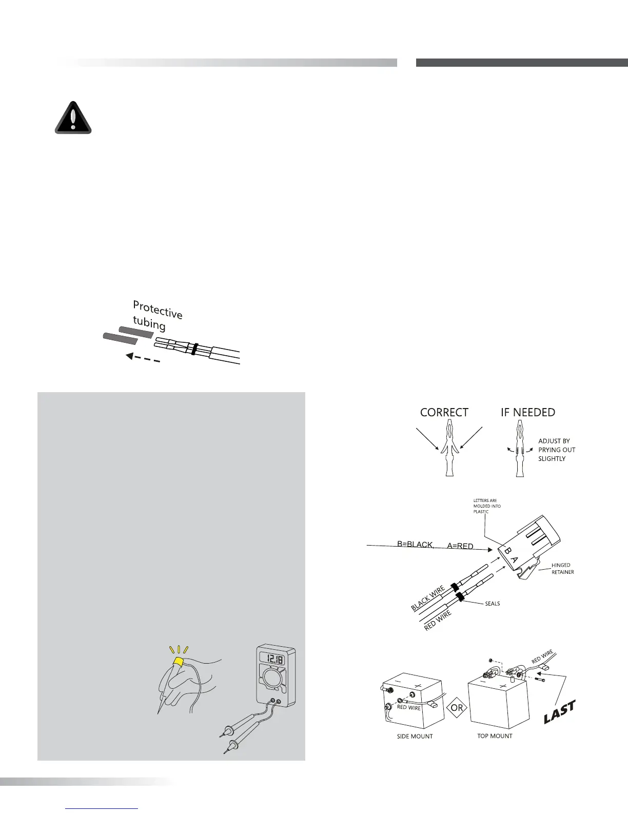
Figure 13-2
Figure 13-4
Figure 13-1
5. Inspect the pin’s retaining anges. The anges
may have been deformed while being run through
the vehicle. These are critical to secure the pins
inside the connector. Adjust as needed. [Figure 13-2]
6. Flip open end connector’s hinged retainer.
• Insert pins as shown. [Figure 13-3]
• Verify the wires cannot be pulled out by
moderately pulling on the wires. Be sure rubber
seals are inside the back of the connector.
• Close the hinged retainer.
• Plug connector into lift.
7. Last, attach red wire to the positive terminal on the
battery. [Figure 13- 4]
NOTE: Troubleshooting with a test light or voltage
meter may give a false indication.
When you probe for 12 volts, the reading may
indicate a connection, even if the connection
is not necessarily sucient. The lift’s motor can
draw up to 20 Amps at some points, requiring all
of the available wire to ow proper current. Poor
connections are the #1 problem associated with a
slow, intermittent, warm, poorly performing motor
which will also deteriorate prematurely.
If a single strand of a multi-strand wire is making
contact, 12V will appear on a meter or test light, but
it will not allow the motor to operate. It is always
best to test both current and voltage, or run the
motor with known
good shop battery or
power source when
troubleshooting.
VOLTAGE
METER
AUTOMOTIVE
TEST LIGHT
4. When harness is through the vehicle, remove
the pin’s protective tubing. [Figure 13-1]
Figure 13-3
CAUTION
If the harness is too long for the vehicle,
coil the excess wire and secure it to
the vehicle frame with the supplied tie
wraps.
Do NOT cut or shorten the harness