10 VCA / VDA / VEA6800+ Installation and Operation Manual
Preliminary—Contents are proprietary and confidential. Do not photocopy or distribute.
Chapter 1: Introduction
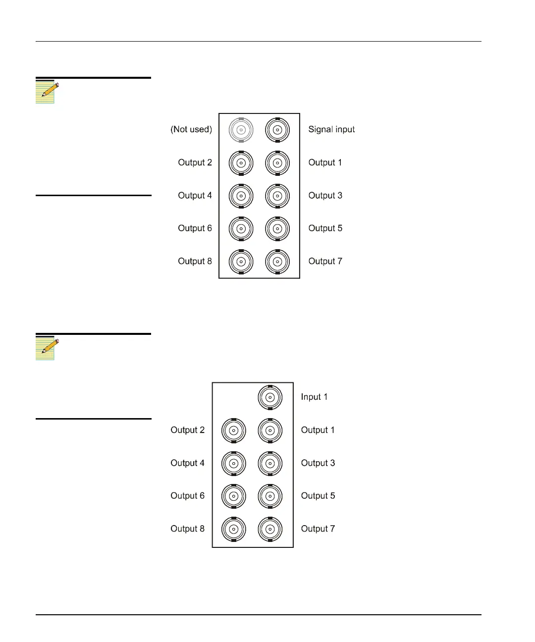
Signal Input/Output Connections for FR6802+DM Frames
Figure 1-6 shows the signal input/output connections used by the
VCA / VDA / VEA6800+ when installed in an FR6802+DM frame.
Figure 1-6. Double-Width Back Module for FR6802+DM Frames
6800/ 7000 Series Frame Back Module (Overlay)
Figure 1-7 shows the double-slot back connector overlay used by a
VCA / VDA / VEA6800+ module when installed in a 6800 / 7000 series
frame.
Figure 1-7. Back Connector for 6800 / 7000 Series Frame
Note
In a DM frame, you can create
looping inputs by adding a
T-connector on the input
connection and changing the
input termination mode jumper
setting to external termination.
(The internal termination setting
is used for non-looping inputs.)
Note
Remote monitoring for the
VCA / VDA / VEA6800+
module is not available if it is
installed in a 6800/7000 series
frame.