18 VCA/VDA/VEA6800+ Installation and Operation Manual
Preliminary—Contents are proprietary and confidential. Do not photocopy or distribute.
Chapter 2: Installation and Configuration
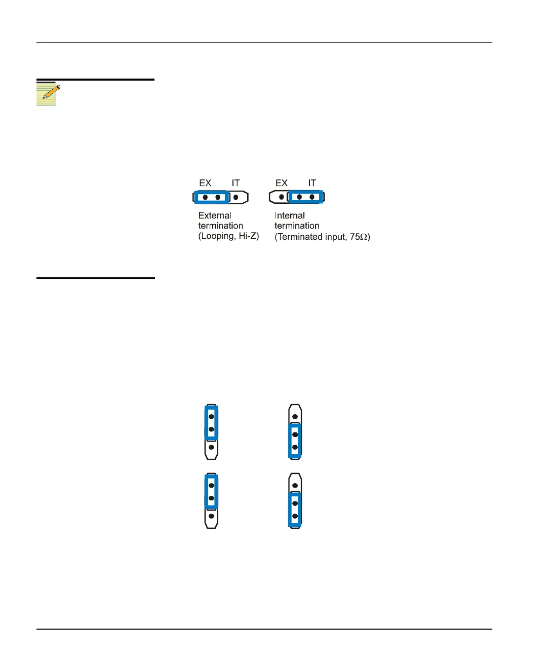
Setting the Input Terminating Jumper
Follow this procedure to set the jumper for looping or internal input
termination:
1. Locate the jumper block on the module. Figure 2-1 on page 17
shows the location of this jumper block.
2. Place the jumper on the pin that corresponds to looping or internal
input termination. See Figure 2-2.
Figure 2-2. VCA6800+ Input Terminating Jumper Block Pin
Placement
Setting the Coupling Mode
Follow this procedure to set the jumper for AC or DC coupling mode:
1. Locate the jumper block on the module. Figure 2-1 on page 17
shows the location of this jumper block.
2. Place the jumper on the pin that corresponds to AC or DC coupling
mode. See Figure 2-3.
Figure 2-3. VCA6800+ Coupling Mode Jumper Block Pin
Placement
Note
In a DM frame, you can create
looping inputs by adding a
T-connector on the input
connection and changing the
input termination mode jumper
setting to external termination.
(The internal termination setting
is used for non-looping inputs.)
For BMFL modules, the input
termination jumper default
mode is for external
termination. This is the setting
you will need if you are using a
looping input.
AC
DC
m
AC
DC
D
m
AC
DC
AC
DC