VCA/VDA/VEA6800+ Installation and Operation Manual 21
Chapter 2: Installation and Configuration
Preliminary—Contents are proprietary and confidential. Do not photocopy or distribute.
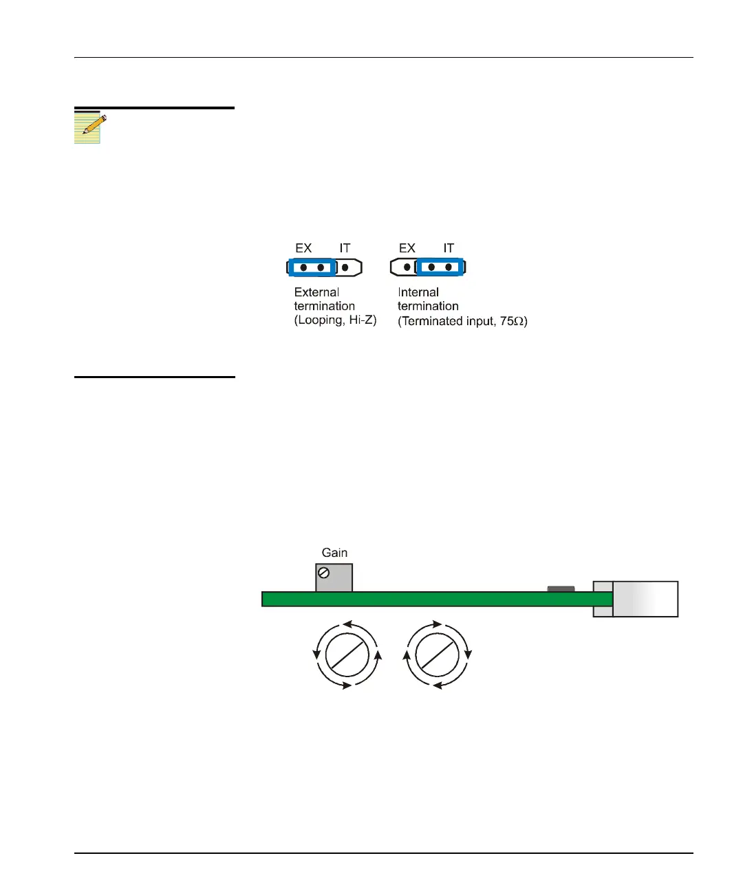
Setting the Input Terminating Jumper
Follow this procedure to set the jumper for looping or internal input
termination:
1. Locate the jumper block on the module. Figure 2-6 on page 20
shows the location of this jumper block.
2. Place the jumper on the pin that corresponds to looping or internal
input termination. See Figure 2-7.
Figure 2-7. VDA6800+ Input Terminating Jumper Block Pin
Placement
Adjusting Potentiometers
The VDA6800+ module has one adjustable pot for gain mode.
Figure 2-6 on page 20 shows the location of this pot. This multi-turn pot
allows you to adjust gain for a range of –3 dB to +3 dB. See Figure 2-8.
• To increase the gain, turn the pot clockwise.
• To decrease the gain, turn the pot counterclockwise.
Figure 2-8. VDA6800+ Gain Mode Potentiometer Adjustment
A single-turn pot allows fine adjustment; an additional single-turn pot
controls response. The adjustments have been set in the
manufacturing facility; readjusting is not recommended without
precision test equipment.
Note
In a DM frame, you can create
looping inputs by adding a
T-connector on the input
connection and changing the
input termination mode jumper
setting to external termination.
(The internal termination setting
is used for non-looping inputs.)
For BMFL modules, the input
termination jumper default
mode is for external
termination. This is the setting
you will need if you are using a
looping input.
VDA6800+
D
r
In
r