41
6.3.3.
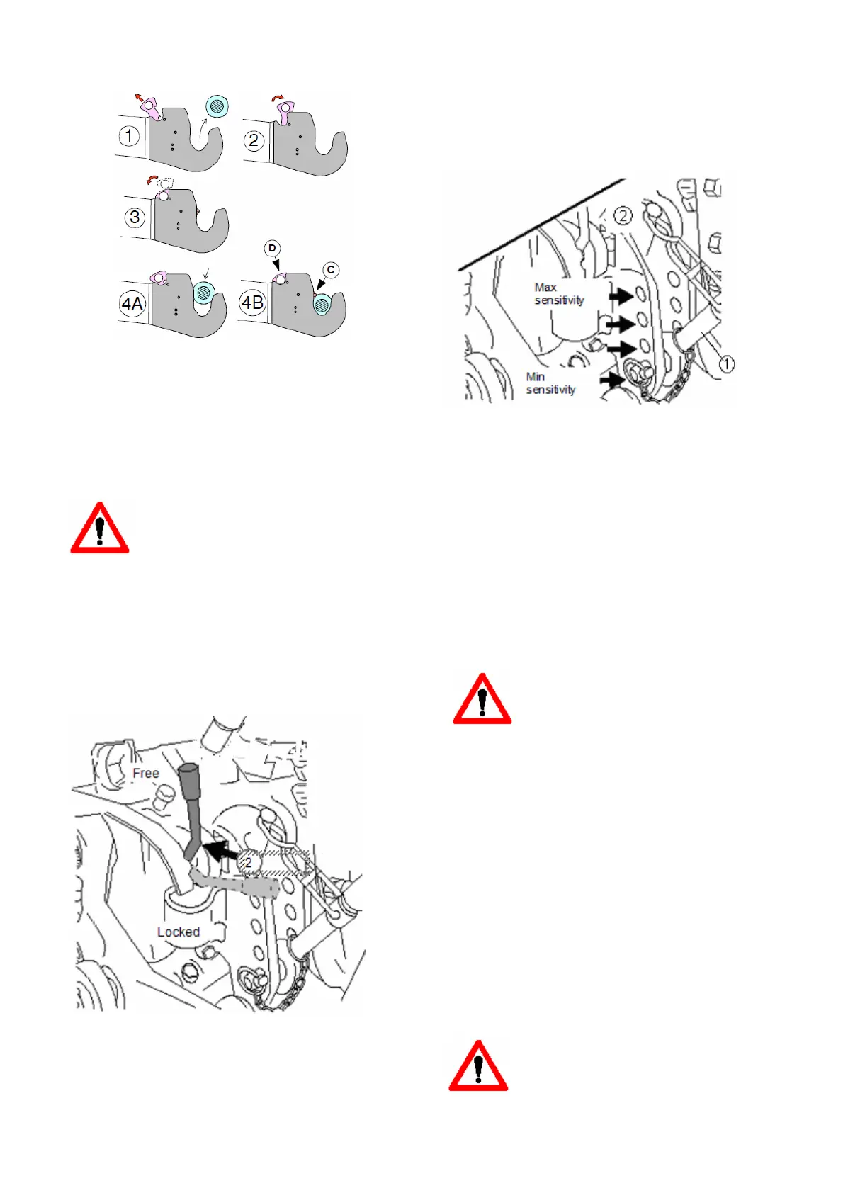
Quick couplings for lower links
1. Pull the lever to release the implement.
2. The lock can be left open by pulling the lever
backward (e.g. for de − mounting an implement).
3. Release the lock by pulling the lever forward.
4. A,B The ball joints lock automatically when
attaching the implement. In the locked position the
clamp (C) is in view and the lever (D) is in the lower
position.
IMPORTANT : Clean if necessary the
quick couplings and ball joints before
the coupling of the implement.
DANGER OF IMPLEMENT UNFASTENINIG!
The quick couplings can be controlled in the cab
using the wire.
6.4. Draft control and automatic weight
transmission (by means of position
lever)
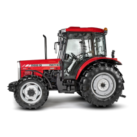
Draft control functions when the impulse sender
lever (2) is in the vertical position.
The draft sensing is regulated by the force in the top
link. The automatic weight transmission acts
together with the draft control.
With increasing draft resistance the hydraulic lift
raises the implement and its weight is partly
transmitted to the rear wheels of the tractor so that
maximum draft is always obtained on the rear
wheels.
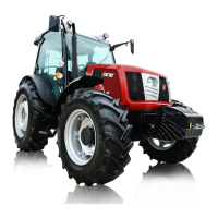
Mechanically controlled hydraulic lift
NOTE: Draft control sensitivity can be altered by
moving the attaching points of the top link (4) on the
tractor. Draft control sensitivity is least when the top
link is connected to the lower hole and greatest
when connected to the upper hole.
Draft control is used when working with soil
penetrating implements (ploughs/plows, cultivators
etc).
NOTE: Semi − mounted and fully mounted
implements can not be exploited with top link
sensitivity.
CAUTION: Only engage draft control with the lever
(2) when there is no load on the three −
point linkage unit (lowest position) and
the position lever is fully in its lowest
position.
Adjust the check links so that the rear end of the
lower links have a play of approx. 70 mm (3 in). The
sideways movement of the implement affects the
draft resistance.
When draft control is not being used the impulse
sender pawl (2) should be in the horizontal position.
6.5. Using PTO shafts
When PTO − powered implements are used, always
make sure that the PTO shaft is of the correct
length, so that it can work at full deflection vertically
and horizontally. If the shaft is too long it will cause
damage. Follow the instructions of the manufacturer
when fitting the shaft.
CAUTION: When fastening the PTO
shaft check that its shield is
undamaged. Always fasten the shield to
a stationary part of the tractor frame or
implement
.